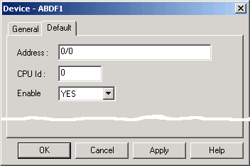
Use the Default tab of the Device dialog box to enter information about DF-1 communications for the device.
|
Enter the node ID for the device.
<Octal digit station address>/< Octal digit station address of the KF2 Module>
<Source ID(00-31)> Note: The Source ID is also knows as the PLC Node address. For special network configurations a KF3 Node address can be used. |
|
|
CPU ID |
Not used. |
|
Select Yes to enable the device when the project starts. Select No to disable the device. If you select No, the device will not be enabled at startup and points associated with the device will not be available. |
|
Step 2.2. Configure Allen-Bradley DF-1 devices. |