|
Movement overview. |
|
|
Movement configuration. |
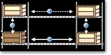
Movement Overview
You can use movement on a CimEdit screen to:
![]() Reflect the change in a value
Reflect the change in a value
![]() Set a value
Set a value
Movement is an effective way to alert an operator that the value of a point or expression changed.
It is easy to make an object move, on the screen and it can be very effective. Because CimEdit provides you with the tools to precisely define your begin and end positions, you have complete control over how the object will move.
Movement involves the relative distance between beginning and ending positions. Therefore, if you use exact location numbers you can still place the object anywhere on the screen and the movement will be the same.
Select the object you want to move.
Open the object's Properties dialog box.
Configure either or both of the following.
|
H |
Horizontal movement. |
|
V |
Vertical movement. |
Movement Configuration
Select Movement in the Properties dialog box.
Runtime horizontal and vertical movement specifications are as follows.
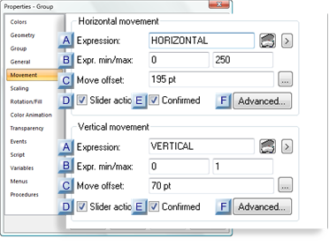
|
Expression |
|
|
Expr min/max |
|
|
Move offset |
|
|
Slider action |
|
|
Confirmed |
|
|
Advanced: Execution Condition |
|
Expression |
A point ID or expression that will determine the object location between the START and END positions.
|
|
Opens the Expression Editor. |
|
|
Opens a Popup menu. |
|
Expr. min/max |
||
|
|
Min |
Minimum value of the point ID or expression. This value or lower will cause the object to be in the START position |
|
|
Max |
Maximum value of the Point ID or expression. This value or higher will cause the object to be in the END position. |
|
Move offset |
The Move offset defines the distance between the object's START position and END position on the CimEdit screen.
The direction can be:
|
Horizontal |
Left to right or right to left. |
|
Vertical |
Bottom to top or top to bottom |
During runtime, CimView calculates the object's location based on the:
![]() Expression minimum and maximum
values,
Expression minimum and maximum
values,
![]() Object's START position and the
offset specification.
Object's START position and the
offset specification.
Do one of the following to calculate the offset.
|
Manual calculation |
|
|
Automatic calculation |
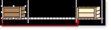
Manual Calculation
When you calculate the offset manually, the object's start/end position is calculated from the following sides.
|
Horizontal |
Calculate from the object's left side. |
|
Vertical |
Calculate from the object's top. |
Status bar
Place the object's top/left side in the START position.
Place the cursor in the object's top/left corner.
Note the Y-axis/X-axis positions in the CimEdit status bar.
Do the same for the object's END positions.
Properties Dialog Box
Place the object's top/left side in the START position.
Open the Properties dialog box for the object.
Select Geometry.
Note the values in the Position Top and/or Left fields.
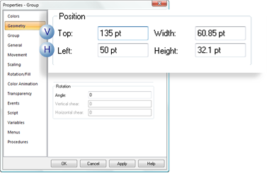
|
|
Position |
Field |
|
H |
Horizontal |
Left |
|
V |
Vertical |
Top |
Close the Properties dialog box.
Do the same for the object's END position.
Subtract the START from the END values.
The value is the distance the object will travel on the CimView screen.
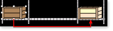
Example: Horizontal
|
END |
245 |
|
START |
50 |
|
Offset value |
195 |
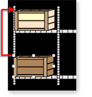
Automatic Calculation
When you calculate the offset automatically, the object's start/end position is calculated from the following sides.
|
Horizontal |
Calculate from the object's horizontal center. |
|
Vertical |
Calculate from the object's vertical center. |
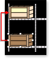
Place the object's center in the START position.
Open the object's Properties dialog box.
Select Movement.
Click the Offset button to the right of the Move offset field.
![]()
The Properties dialog box closes.
Click the END position on the CimEdit screen that will be the center of the object.
The Properties dialog box re-opens with the START to END value entered in the Move offset field.
![]()
|
Slider action |
Check to enable runtime users to set an analog point by moving the object horizontally on the CimView screen.
Important: The slider action is enabled for analog or real points only.
During runtime when a slider object is released, its position between the beginning and end of the horizontal or vertical distance that you specify represents the value that will be written to the point or points.
You can use the slider action alone or combine it with other procedures.
When you do, the order of execution is:
The Mouse down procedure, if defined, runs.
The Slider action runs.
The Mouse up procedure, if defined, runs.
|
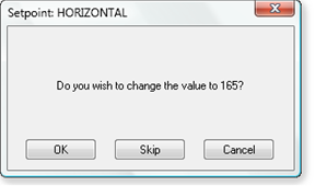
Confirmed |
Check to have CimView display a message asking a user for confirmation to move the object.
Example
|
Advanced: Execution Conditon |
Click the button to open an Execution Condition dialog box.
The execution condition directs CimView to disable the slider action if an entered expression is False.
Specifications are as follows.
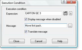
|
Option |
Description |
|
Expression |
One or more point ID's and mathematical operators that can be evaluated. The expression must evaluate to TRUE during runtime in order for a user to access the Setpoint action. |
|
Display message when disabled |
(Available if an expression is entered in the Expression field) Displays the entry in the message during runtime when a user attempts to perform the Setpoint action and the Execution Condition Expression evaluates to FALSE. |
|
Message |
String that displays in a Message box during runtime when a user attempts to perform the Setpoint action and the Execution Condition Expression evaluates to FALSE.
|
|
Translate message |
The message text string can be translated or revised for selected languages in the CIMPLICITY Language Mapper file. The translation or revised text display in CimView when the assigned language is selected |
Execution Condition evaluated for a Slider action
|
When an Execution Condition is evaluated as: |
|
|
True |
The procedure behaves normally |
|
False and No message is defined |
The system behaves as if the procedure does not exist. |
|
|
Example If the procedure is assigned to a key, nothing will happen when the user presses the key. |
|
False and A message is defined |
A user may think the procedure exists. However, when the user selects the procedure, the message displays and the procedure will not run. |
|
|
If the expression contains unavailable points, a user may think a procedure exists. However, when the user selects the procedure, the following message displays. |
|
|
"The execution condition for this procedure contains unavailable points. Would you like to execute the procedure anyway?" |
|
If the user selects: |
|
|
Yes |
The procedure can be performed |
|
No |
The procedure is not performed |
Examples of how an Execution Condition is Used
If a custom application provides security information as a CIMPLICITY point, this feature can be used to provide security control for procedure execution.
If an application runs in modes, such as Manual and Automatic, this feature can be used to disable certain procedures while in Automatic mode.
![]() Note: The object will not begin to move
until the minimum value has been exceeded.
Note: The object will not begin to move
until the minimum value has been exceeded.
|
|
Runtime movement and animation |