|
Rotation overview |
|
|
Rotation configuration |
|
|
Runtime example |
Rotation Overview
You can make the following objects rotate during runtime based on the value of one or two expressions.
![]() Lines
Lines
![]() Shapes
Shapes
![]() Text
Text
![]() Buttons
Buttons
![]() Groups
Groups
![]() Frames
Frames
![]() Note: One of the many useful applications for
rotation is to place one or more gauges on the screen. The CimEdit
Smart Object library provides you with gauges for which you only
need to enter the expression they represent. During runtime, they
will rotate to reflect the expression's value.
Note: One of the many useful applications for
rotation is to place one or more gauges on the screen. The CimEdit
Smart Object library provides you with gauges for which you only
need to enter the expression they represent. During runtime, they
will rotate to reflect the expression's value.
Select the object you want to rotate.
Open the object's Properties dialog box.
Configure the rotation.
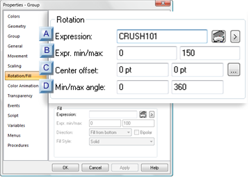
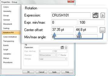
Rotation Configuration
Select Rotation in the Properties dialog box.
Rotation options are as follows.
|
Expression |
|
|
Expr. min/max |
|
|
Center offset |
|
|
Min/max angle |
|
Expression |
A point ID or expression that will determine the object location between the START and END positions.
|
|
Opens the Expression Editor. |
|
|
Opens a Popup menu. |
|
Expr. min/max |
||
|
|
Min |
Minimum value of the point ID or expression. This value or lower will cause the object to have no rotation. |
|
|
Max |
Maximum value of the Point ID or expression. This value or higher will cause the object to rotate to the maximum angle. |
![]() Note: If the Expression field contains a single
point ID with no operations performed on it and the point has
Display Limits defined, you may leave the Expr. Min/Max fields blank.
Note: If the Expression field contains a single
point ID with no operations performed on it and the point has
Display Limits defined, you may leave the Expr. Min/Max fields blank.
CimView will use the Display Limits configured for the point ID for the expression minimum and maximum values when the screen file opens.
|
Center offset |
The Center offset specifies the x, y offset values where the center of the object will display during runtime.
![]() Offset
guidelines
Offset
guidelines
![]() Negative or positive numbers can
be entered in either field.
Negative or positive numbers can
be entered in either field.
![]() The higher the entry the further
the object will display from the object center.
The higher the entry the further
the object will display from the object center.
![]() 0,0 will cause the object to have no rotate in its
default position.
0,0 will cause the object to have no rotate in its
default position.
Manual Offset
Enter the values that the object will be offset as follows.

|
X |
Center offset from the expression value along the X axis. |
|
Y |
Center offset from the expression value along the Y axis. |
Automatic Offset
Click the Quick
Offset button ![]() to the right of the Center Offset field.
to the right of the Center Offset field.
The dialog box closes temporarily.
Move the cursor on the CimEdit screen to the where you want the center of rotation
Hold down the left-mouse button.
The cursor turns into a crosshair, indicating the object center location, surrounded by a circle.
The further the cursor moves from the original object center, the larger the circle becomes.
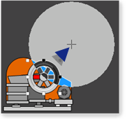
Release the left-mouse button.
The Properties dialog box re-opens.
The coordinates established when the mouse button was released, display in the Center Offset fields.
|
Min/Max angle |
The Min/Max angle fields specify the object's minimum/maximum angles of rotation for the minimum/maximum expression values.
![]() Negative or positive numbers can
be entered.
Negative or positive numbers can
be entered.
![]() The following values cause the to
perform one full rotation around the center offset as the
expression value increases from its minimum value to its maximum
value.
The following values cause the to
perform one full rotation around the center offset as the
expression value increases from its minimum value to its maximum
value.
|
Rotation |
Min |
Max |
|
Clockwise |
0 |
-360 |
|
Counter clockwise (default) |
0 |
360 |
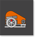
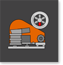
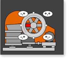
Runtime Example
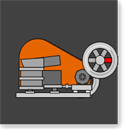
A jaw crusher's wheel rotation has the following specifications
|
Exp. min/max |
0, 100 |
|
Min/max angle |
0, -360 |
![]() When the offset values are entered
as 0, the wheel rests on the crusher
with the red spoke to the left.
When the offset values are entered
as 0, the wheel rests on the crusher
with the red spoke to the left.
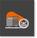
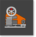
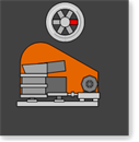
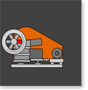
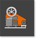
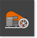
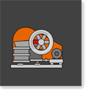
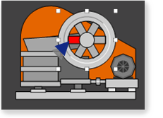
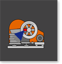
![]() A center offset other than 0, 0
would move the wheel around the crusher, based on the expression
value, as follows
A center offset other than 0, 0
would move the wheel around the crusher, based on the expression
value, as follows
|
|
Minimum/maximum angles |
|||
|
Value |
0/25 |
0/-25 |
25/0 |
-25/0 |
|
25 |
|
|
|
|
|
50 |
|
|
|
|
|
75 |
|
|
|
|
|
0 or 100 |
|
|
|
|
|
|
Runtime movement and animation |