The device point's data type choices are on the General tab of the Point Properties dialog box. The data type choices available to you for a device point depend on the type you selected when you created it.
Basic general specifications include the following:

|
Description |
|
|
Data type |
|
|
Elements (in an array) |
|
|
Read only |
|
Description |
(Optional) Enter a Description up to 80 characters.
This description:
![]() Displays when you position the
cursor over the point in the Workbench
Displays when you position the
cursor over the point in the Workbench
![]() Can be entered in the Point
browser when you want to find and display or use the point
Can be entered in the Point
browser when you want to find and display or use the point
|
Data type |
Select one Data Type from the drop down list that displays for the point type you selected:
The Data Types are:
|
Analog device points. |
|
|
Boolean device points. |
|
|
Text device points. |
Analog device points

|
Data Type |
Description |
|
DINT |
4 byte (32 bit) ranging from -2,147,483,648 to + 2,147,483,647. |
|
INT |
Integers ranging from -32,768 to +32,767. |
|
REAL |
Floating-point numbers. |
|
SINT |
Integers ranging from -128 to +127. |
|
UDINT |
Unsigned integers ranging from 0 to 4,294,967,295. |
|
UINT |
Unsigned integers ranging from 0 to 65,535. |
|
USINT |
Unsigned integers ranging from 0 to 255. |
|
3D_BCD |
3-digit binary coded, 2 byte (16 bit) unsigned integer ranging from 0 to 999. |
|
4D_BCD |
4-digit binary coded, 2 byte (16 bit) unsigned integer ranging from 0 to 9999. |
Note: Values read from or written to a device point will be forced into the specified type.
Example
Reading an SINT point value, which is 8-bits, from a 16-bit register will truncate the high order byte, and the sign will not be maintained.
Writing an INT point, which is 16-bits, to an 8-bit register will do the same.
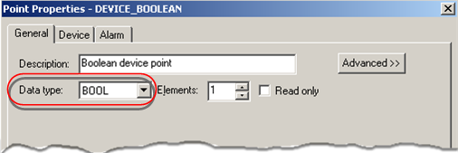
Boolean device points
|
Data Type |
Description |
|
BOOL |
A one digit Boolean point with a value of 0 or 1. |
|
BYTE |
8-bits of data |
|
WORD |
16 bits of data |
|
DWORD |
32 bits of data |
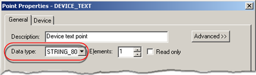
Text device points
|
Data Type |
Description |
|
STRING |
A one character alphanumeric |
|
STRING_20 |
A 20 character alphanumeric string |
|
STRING_8 |
An 8character alphanumeric string |
|
STRING_80 |
An 80 character alphanumeric string |
|
Elements (in an Array) |
CIMPLICITY software treats all points as array points.
You can define single points and array points. Using array points is one way to provide more efficient data collection. An array point can represent one instance of several process variables, or several instances of one process variable.
Enter:

|
A |
1 |
The array is a single element array |
|
B |
2 or more |
The array is a multiple element array. |
![]() Important: Array points are not
supported by all CIMPLICITY software functions. Support for array
points is as follows:
Important: Array points are not
supported by all CIMPLICITY software functions. Support for array
points is as follows:
|
CimEdit |
Objects can be configured to display array elements and use them for movement or animation |
|
CimView |
Array elements can be displayed, and can control movement or animation. |
|
Alarm Viewer |
Alarms cannot be generated for array points. |
|
Database Logger |
Individual array elements can be logged. |
The maximum size of an array point depends on the:
![]() Device type being used
Device type being used
![]() Memory type being addressed
and
Memory type being addressed
and
![]() Point type.
Point type.
The maximum size of an array point for each device type is:
|
Device Type |
Maximum Size |
|
Virtual |
1600 bytes |
|
CCM2 |
250 bytes |
|
Genius datagram |
128 bytes |
|
Series 90 TCP/IP |
1000 bytes |
|
SNP and SNPX |
200 bytes |
|
Allen-Bradley Communications |
1000 bytes |
|
Data Highway Plus |
1000 bytes |
|
Applicom |
250 bytes |
|
DDE |
1000 bytes |
|
FloPro/FloNet |
240 bytes |
|
Johnson Controls N2 |
16 bytes |
|
Mitsubishi A-Series Serial |
1000 bytes |
|
Mitsubishi TCP/IP |
512 bytes |
|
Modbus Plus |
1000 bytes |
|
Modbus RTU |
1000 bytes |
|
Modbus TCP/IP |
512 bytes |
|
OMRON Host Link |
1000 bytes |
|
OMRON TCP/IP |
1000 bytes |
|
Seriplex |
480 bytes |
|
Sharp TCP/IP |
1000 bytes |
|
Siemens TI |
250 bytes |
|
Smarteye Electronic Assembly |
250 bytes |
|
Square D SY/MAX |
250 bytes |
The Smarteye and DDE Client protocols do not support array points.
Values read from or written to a device point are forced into the correct type of the point. This may affect the array size.
Example
An analog point is an INT data type on a CCM2 device.
The maximum array size in Register memory is 125 elements because each point in the array is put into a separate 16-bit register.
Check the appropriate Device Communications documentation for further information.
|
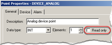
Read only |
|
Option |
Description |
|
Clear |
The point can be used as a set point. |
|
Checked |
The point cannot be used as a set point. |
![]() Note: When a read-only device point is put in
manual mode , the read-only feature is ignored. As a result, if
Allow set point for read only manual mode
points is checked (enabled) in the Point Setup dialog box that is accessed through the Project Properties dialog box, administrators
who are performing system diagnostics can change its value for
testing purposes.
Note: When a read-only device point is put in
manual mode , the read-only feature is ignored. As a result, if
Allow set point for read only manual mode
points is checked (enabled) in the Point Setup dialog box that is accessed through the Project Properties dialog box, administrators
who are performing system diagnostics can change its value for
testing purposes.
|
|
Step 2. Enter device point general properties. |