Once you have isolated and named the tracking regions on your diagram, you must define all the possible routes through which products can flow.
Each route will subsequently be associated with a CIMPLICITY point that will send a signal to the tracking model when an item has passed down a specific path.
For this function, it is recommend that you use positive ID switches; however, existing hardware or special production conditions may require that a limit switch be used instead. An operator interface or some other data collection device will normally set the point associated with a route.
Using your tracking region diagram, indicate each and every possible route within the production process. Be sure to include routes to scrap or detainment regions as well.
Example
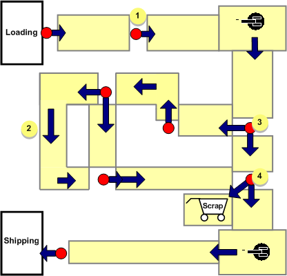
All routes are defined on the tracking region diagram using direction arrows.
Every possible route is indicated, including the area for scrapped goods. Multiple paths are clearly illustrated on the diagram.
|
1 |
Production flow stems from operator interfaces and other devices |
|
2 |
Direction arrows to show product flow and define routes. |
|
3 |
Multiple routes from one device. |
|
4 |
Every possible route, including detainment or scrap regions. |
|
|
Production Tracking Model layout plans. |