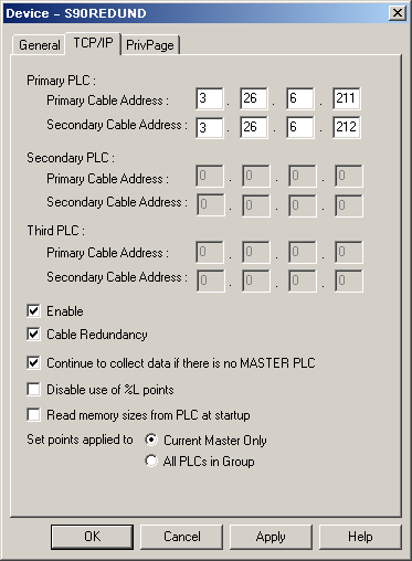
Use the TCP/IP tab in the Device Properties dialog box to enter information about TCP/IP communications for the device.
You can define the following.
|
Primary PLC of the redundant group: |
|
|
Primary Cable Address |
Enter the IP address of the primary Ethernet card in the Primary PLC Primary Cable Address field. |
|
Secondary Cable Address |
This field is available only if you select the Cable Redundancy option and a redundant PLC model. Enter the IP address of the secondary Ethernet card in the Primary PLC Secondary Cable Address field. |
|
Secondary PLC: Duplex or Triplex selected for the device model |
|
|
Primary Cable Address |
Enter the IP address of the primary Ethernet card in the secondary PLC Primary Cable Address field. |
|
Secondary Cable Address |
This field is available only if you select the Cable Redundancy option. Enter the IP address of the secondary Ethernet card in the secondary PLC Secondary Cable Address field. |
|
Third PLC: Triplex selected for the device model |
|
|
Primary Cable Address |
Enter the IP address of the primary Ethernet card in the Third PLC Primary Cable Address field. |
|
Secondary Cable Address |
This field is available only if you select the Cable Redundancy option. Enter the IP address of the secondary Ethernet card in the Third PLC Secondary Cable Address field. |
|
Device options include |
|
|
Enable |
Select this check box to enable the device when the project starts. If you clear this check box, the device will not be enabled and points associated with the device will be unavailable. |
|
Cable Redundancy |
Select this check box if redundant cabling is being used for this device. If you clear this check box, the Secondary Cable Address fields in this dialog box are disabled. This option is available only for redundant PLC model types. |
|
Continue to Collect Data if there is No Master PLC |
By default, when the Series 90 TCP/IP Redundant Communications enabler loses its connection to the master PLC of a redundant group and the slave PLC(s) fail to set its Master bit, the enabler marks the device down. All points go (and remain) "Unavailable" until one of the PLCs declares itself the master. You can select this check box to change this behavior so that when the master PLC of a redundant group fails, and no other PLC declares itself the master, the enabler automatically starts collecting data from the highest-ranking slave PLC. This option is available only for redundant PLC model types. |
|
Disable use of %L points |
By default, the Series 90 TCP/IP Redundant Communications enabler validates %L device points by reading Program Blocks from the PLC. This may increase the length of time it takes to start the enabler. If you do not use %L points in your project, you can change the enabler, via selecting the corresponding button, to skip this validation. This option is available only for Series 90-70 PLC models (standard or redundant). |
|
Read Memory Sizes from PLC at Startup |
On start up, the Series 90 TCP/IP Redundant Communications enabler must obtain the size of each Memory type in the PLC. The enabler saves this configuration for faster initialization on subsequent starts. By default, the enabler will use this saved configuration instead of reading the configuration from the PLC. You can change the enabler, via selecting the corresponding button, to obtain the sizes from the attached PLC. |
|
Set Points Applied to |
By default, the Series 90 TCP/IP Redundant
Communications enabler only reads data from and writes data to the
active master. You can change the enabler, via selecting the
corresponding button, to write data to all the programmable
controllers in the redundant group. |
|
|
Series 90 TCP/IP Triplex device configuration. |