The LD editor is a powerful graphical tool that enables you to enter and manage Ladder Diagrams according to the IEC 61131-3 standard. The Free form Ladder editor enables free drawing and arrangement of LD items, and supports advanced graphic features such as drag and drop.
| LD
diagram components: |
Related sections: |
| Networks Power rail and lines Contacts and coils Function blocks Data In/Out Jumps and RETURN |
Selection grid Moving and copying items Managing comment texts
|
Note: When a contact or a coil is selected, You can press the SPACE bar to change its type (normal, negated, pulse...)
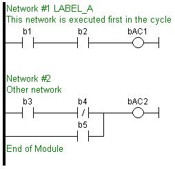
A program is entered as a list of independent networks. Networks are executed sequentially from the top to the bottom. The head of a network is drawn on a full row in the editor, grouping the following pieces of information:
- the number of the network (from 1 to N)
- an optional label name used as a target for jump operations
- an optional directive for conditional
compiling
- an optional multiline description (comment)
No item can be put on a network header row. No line can go through it. The end of a program is marked with a special "End of module" row. Nothing can be inserted after this row.
Double click on the header of a network to enter its label, directive and description. New networks can be inserted on empty rows. Pressing "DEL" when the first network is selected removes the network and its whole contents. In case of another network, its contents is merged with the previous network.
There cannot be two networks having the same label in a program. If such a situation occurs in case of a copy operation, you will be prompted to:
- either specify another label name for the new network
- or remove the label on the new network.
Vertical power rails are used in LD language for representing the limits of a rung. The power rail on the left represents the TRUE value and initiates the rung state. Any object connected to this rail is always powered.
Horizontal lines always represent a data flow from the left to the right.
If a vertical line has several items connected on the left, then it represents an "OR" operation.
You can insert at any location a segment of horizontal line in order to freely draw flow lines. The "vertical line" button enables you to set or remove (toggle) a segment of vertical line on the right of the selected cell.
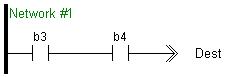
Contacts are basic graphic elements of the LD language. A contact is associated to a boolean variable written upon its graphic symbol. A contact sets the state of the rung on its right side, according to the value of the associated variable and the rung state on its left side.
Below are the possible contact symbols and how they change the flow:
| boolVariable -] [- |
Normal:
the flow on the right is the boolean AND between the flow on the
left and the associated variable. |
| boolVariable -]/[- |
Negated:
the flow on the right is the boolean AND between the flow on the
left and the negation of the associated variable. |
| boolVariable -]P[- |
Positive
pulse: the flow on the right is TRUE only when the flow on the left
is TRUE and the associated variable changes from FALSE to TRUE
(rising edge) |
| boolVariable -]N[- |
Negative pulse: the flow on the right is TRUE only when the flow on the left is TRUE and the associated variable changes from TRUE to FALSE (falling edge) |
Note: When a contact or a coil is selected, You can press the SPACE bar to change its type (normal, negated, pulse...)
Two serial normal contacts represent an AND operation. Two contacts in parallel represent an OR operation.
Coils are basic graphic elements of the LD language. A coil is associated to a boolean variable written upon its graphic symbol. A coil performs a change of the associated variable according to the flow on its left side.
Below are the possible coil symbols:
| boolVariable -( )- |
Normal:
the associated variable is forced to the value of the flow on the
left of the coil. |
| boolVariable -(/)- |
Negated:
the associated variable is forced to the negation of the flow on
the left of the coil. |
| boolVariable -(S)- |
Set: the
associated variable is forced to TRUE if the flow on the left is
TRUE. (no action if the flow is FALSE) |
| boolVariable -(R)- |
Reset: the associated variable is forced to FALSE if the flow on the left is TRUE. (no action if the rung state is FALSE) |
Note: When a contact or a coil is selected, You can press the SPACE bar to change its type (normal, negated, pulse...)
Important notes: Although coils are commonly put at the end, the rung may be continued after a coil. The flow is never changed by a coil symbol.
Functions and function blocks can be used in LD diagrams. Blocks are always connected to the flow line (powered) by their first input and first output. If the first input of a block is not boolean, a special input called "EN" is added, and means that the block is not executed if the input flow is FALSE. If the first output is not boolean, a special output called "OK" is added. The special "OK" output always has the same state as the first input (the flow).
In case of a function block, the instance of the block must be specified and is shown on the top of the block. Double click on the top of the block to select the instance. You can also double click somewhere else in the block to change its type.
Boolean inputs and outputs of blocks can be directly linked to contacts and coils. Block inputs and outputs can also be specified using specific data in/out items (see below).
The "data in" and "data out" items are used to initiate a flow (line) with the value of a variable, or to force a variable on output with the value of a flow:
VarIn>- .......... ->VarOut
When used with a block, the "data in" and "data out" items can be put close to the block without any line in between to connect a variable to an input or output of the block.
A jump to a label branches the execution of the program after the specified label. In LD language, the ">>" symbol, followed by the target label name, is used as a coil at the end of a rung:
The jump is performed only if the rung state on input is TRUE. The destination label must be specified on a network of the same program. The special "<RETURN>" destination specifies a jump to the end of the program.
The diagram is entered in a logical grid. All objects are snapped to the grid. You can use the commands of the View menu for displaying of hiding grid points. This helps you locating errors detected by the compiler, or aligning objects in the diagram. At any moment you can use the commands of the View menu for zooming in or out the edited diagram. You also can press the [+] and [-] keys of the numerical keypad for zooming the diagram in or out. You also can drag the separation lines in vertical and horizontal rulers to freely resize the cells of the grid:
The current position in the grid is always highlighted by a dotted cell:
![]()
If you click on the current position, then the cell is drawn as grey, meaning that it can be dragged somewhere else in the diagram (see below). You also can select multiple cells with the mouse, or using the arrows of the keyboard with the SHIFT key pressed.
Click on the left border (grey ruler) to select a full row.
Other selection commands are available from the beyboard:
|
Ctrl + Page Up Down |
moves the caret to previous or next network header |
|
Shift + Ctrl + Page Up Down |
moves the caret to the beginning or the end of the program |
|
Home |
moves the
caret to the left of the line |
|
End |
moves the
caret to the end of the line |
| Ctrl + A | selects the whole network if pressed again, selects the whole program |
When you click on the current position, then the cell is drawn as grey, meaning that it can be copied or moved. Click again on the selection to drag it with the mouse.

Dragging the selected items moves them to the specified location. If you press the "CTRL" key while dragging, then items are copied.
To move a function block, you must select it entirely.
If you move or copy items on a non empty area, you wlll be prompted t confirm the overwriting of items in the area.
When you move or copy items just upon a network header, the network is automatically moved in order to give the required extra space for moved items.
The "Copy / Cut / Paste" commands can also be used as an alternative to drag and drop.
A rectangular selection within the diagram cannot go cross a network header, i.e. all selected items must be within the same tework. To select a complete network or more, you must select complete rows. For that, move the caret to the left border or click on the left side ruler (grey).
Multiline comment texts may be entered on any network header. Commands are available for importing or exporting comment texts to/from text files. This feature enables easy localization of programs.
When exporting comment texts, each comment block will be identified in the text file by a number. You have the selection to use for this number:
- the internal "index number" of
networks,
- or the visible network number of networks.
The first method using internal index numbers should be preferred, as such numbers are kept when networks are moved or removed.
When importing comment texts you have the selection of either updating only comment texts of networks found in the import text file, or cleaning all comment texts not found in the import file.