Profinet IO Configuration
The workbench contains a fully integrated configurator for Profinet IO RT. Please refer to the following topics to find the requested information:
Data exchange -
configuration
Configuration
Data types
Additional features
Note:
Referring to the Profinet standard the units of a Profinet network are named as IO Controllers (Profibus: Masters) and IO Devices (Profibus: Slaves).
Data exchange - configuration:
The Runtime manages a mapping table which contains the Profinet IO Inputs and Outputs.
An appropriate configuration tool is integrated in the Workbench. To start the configuration choose File > Open > Fieldbus Configuration. The fieldbus configuration window opens.
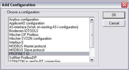
Choose Insert > Insert Configuration…
The following window opens. Select"PROFIONET IO" and click OK.
The configuration is represented as a tree:
- Profinet IO
Configuration
- Profinet IO controller
(*)
- Profinet IO device
(*)
-
Variable
(*)
(*) These items can appear several times in the configuration (depending on the bus topology).
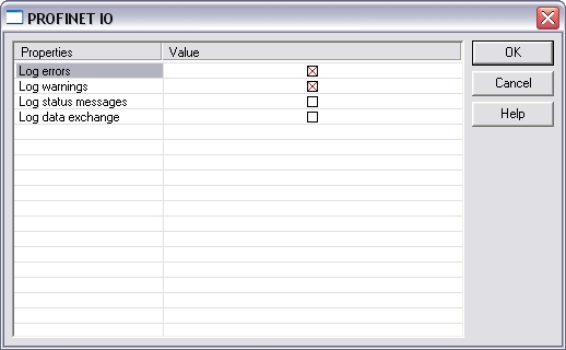
With a double click on the configuration item the depth of the logging can be adjusted.
The I/Os of the Profinet network must be connected to the variables via a Profinet IO controller. Start the declaration of a Profinet controller with Insert > Insert Master/Port... The following window opens:
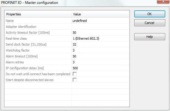
These parameter can be changed:
| Name | Free description text |
| Adapter identification | MAC address of the Profinet IO controller or name of the network connection (Windows XP or younger and Windows CE 4.1 or younger). Use the name of the network connection in order to run the Runtime redundantly. The name of the network connection can be found in the system panel of the operationg system (e.g.: LAN-connection). |
| Activity timeout factor [100ms] |
Timeout for the connection establishment to the devices (maximum time between beginning of connection establishment and the first cyclic data exchange); Timeout factor based on 100ms |
| Real-time class |
Class 1: cyclic data
exchange without priority tag |
| Send clock factor [31,250µs] | Send clock factor. Multiple of 31,250µs (32 = 1ms) |
| Watchdog factor |
Watchdog factor (default 3): |
| Alarm timeout [100ms] |
Alarm timeout (default
50) |
| Alarm retries |
Number of alarm retries (default
3) |
| IP configuration delay [ms] |
IP configuration delay (default
500): |
| Do not wait until connect has been completed |
On: the application starts
immediately |
| Start despite disconnected slaves |
On: the application starts despite
configured but not found devices |
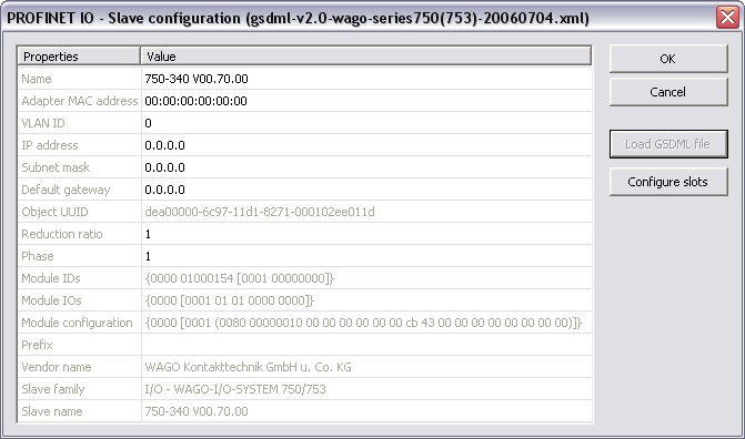
Mark the controller and click Insert > Insert Slave/Datablock... to add a Profinet IO device.
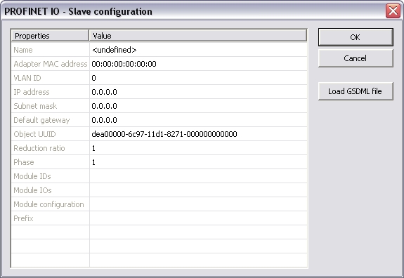
These parameter can be changed:
| Name |
A device name can consitst of
labels and must follow these conventions: |
| Adapter MAC address | MAC address of the Profinet IO device |
| VLAN ID | Virtual LAN ID |
| IP address | IP address of the device |
| Subnet mask | Subnet mask for the IP address of the device |
| Default gateway | Default gateway |
| Object UUID | UUID of the device |
| Reduction ratio |
Reduction ratio (default 1): |
| Phase | Phase |
| Module IDs | Module IDs of the device modules |
| Module IOs | Module IOs of the device modules |
| Module configuration | Module configuration |
| Prefix | Prefix for the variables |
Note:
With the calculation of <Watchdog factor> * <Reduction
ratio> * <Send clock factor> * 31,250 µs you get the time
that may expire between two frames until the device is set back.
I.e. for the default settings 3 * 1 * 32 * 31,250 µs the connection
will be set back after 3ms of missing frames. For office networks
this time is rather low. It is recommended to us a Reduction ratio
of 32 and a Watchdog factor of 24 for office networks. I.e. the
connection will be reset after 24 * 32 * 32 * 31,250 µs = 768 ms.
If this data exchange rate is to low please separate the PROFINET
IO network from the office network (e.g. by a router).
Click "Load GSDML file" to import the necessary GSDML file.
Do the slot configuration after the GSDML file import.
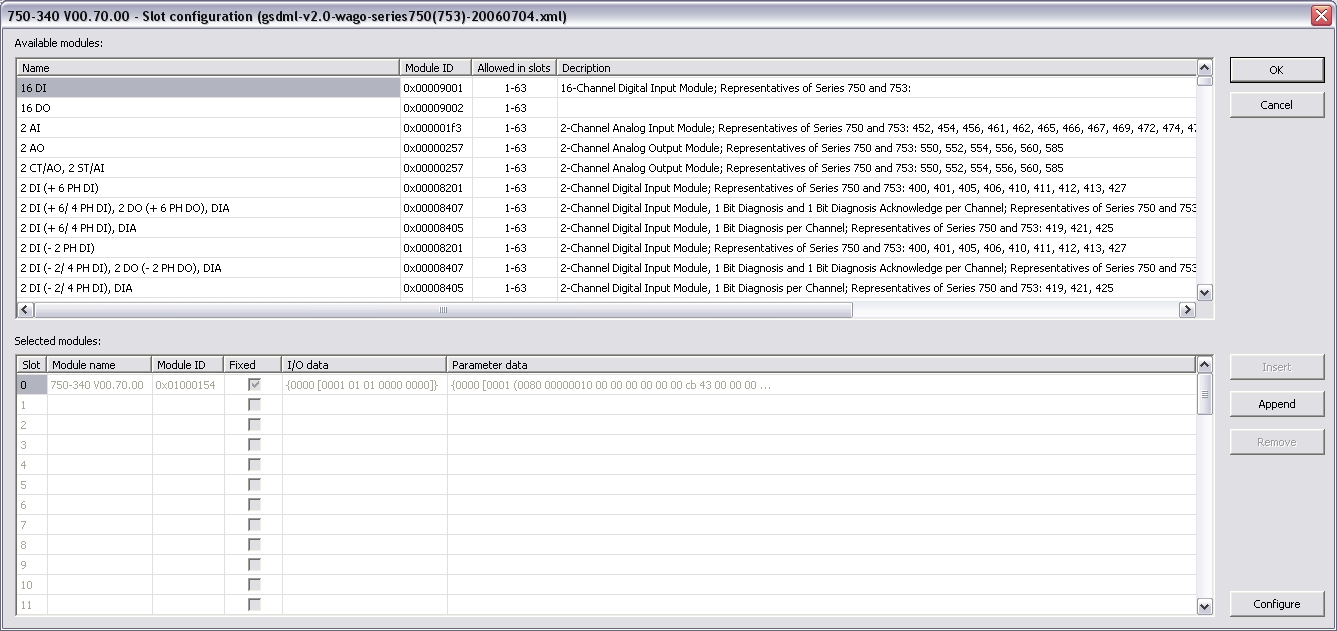
Select the modules in the upper list. With the buttons "Insert" and "Append" the modules are copied to the lower list.
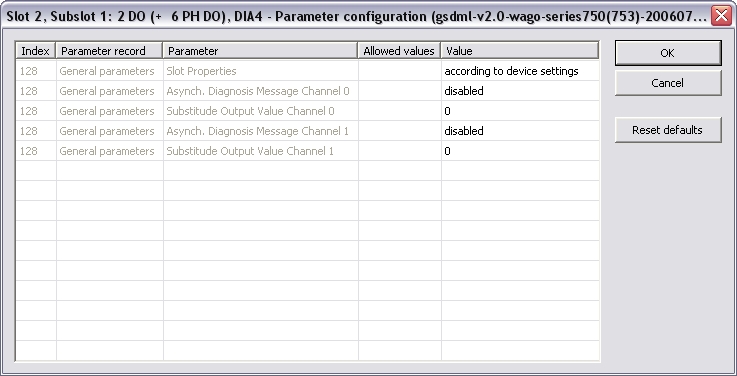
You can not configure each module. Only modules with some sub modules respectively with a sub module with parameter data can be configured. Mark the according module in the lower list and click the "Configure" button.
Example:
Now you can connect the variables with the I/Os. Use Insert > Insert/Set Variable... in order to append a variable to a device.
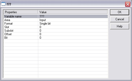
These parameter can be changed:
| Variable name | Variable name following the IEC 61131-3 syntax |
| Area | Output, Output IOCS, Output IOPS, Input, Input IOCS, Input IOPS, device status |
| Format | 32 bit float, Signed 16 bit integer, Signed 32 bit integer, Signed 8 bit integer, Single bit, Unsigned 16 bit integer, Unsigned 32 bit integer, Unsigned 8 bit integer |
| Slot | Slot Number |
| Subslot | Subslot Number |
| Offset | Offset |
| Bit | Bit |
Note: The offset of a variable is relative to a sub module. Thus also depending from a slot and subslot. The offset of the first variable of a sub module is always 0.
All settings can be changed in the grid too. Click View > Grid in order to show/hide the grid. The information show refers to the items below of the selected item in the configuration tree.
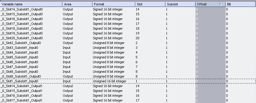
If the Workbench is online with a target system the grid shows the real-time data of the variables.
You can connect variables of any data type to the Profinet I/Os. The Runtime converts the values of the I/Os to the type of the variable. STRING variables are not supported.
“Browse network adapters”:
This command is available in the context menu of the Profinet IO
configuration item. All available network adapters are listed
up.
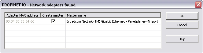
Select the right network adapter and click OK.
Click Edit > Properties... to change the properties of the selected network adapter.
“Browse
network for slaves”:
This command is available in the context menu of the network
adapter. All connected Profinet IO devices are listed up.
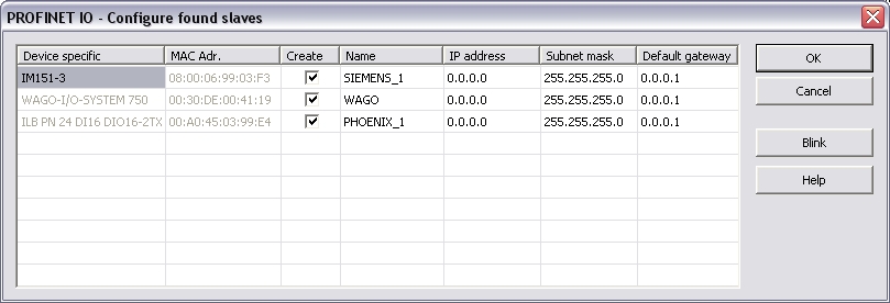
Select the devices you want to add in the tree via the checkbox in the column "Create".
The Network Link (or another) -LED of the marked device blinks for three seconds when pressing the "Blink" button.
Set the device names (column "Name") here!
Do not change this names later!
A device name can consitst of labels and must
follow these conventions:
- 1 or more labels, separated by [.]
- Total length is 1 to 240
- Label length is 1 to 63
- Labels consist of [a...z0...9-]
- Labels do not start with [-]
- Labels do not end with [-]
- The first label does not start with "port-xyz" or
"port-xyz-abcde" with a,b,c,d,e, x, y, z = 0...9
- Device names do not have the form n.n.n.n, n = 0...999
- Labels do only start with 'xn-' if RFC 3490 is applied
Set the IP address of the device here. By clicking into the grid the Default gateway will be set automatically.
Click OK after setting the IP-parameters (address, subnet mask, default gateway).
Configuration of devices
After
adding the Profinet devices to the controller they need to be
configured. Double click on the referring device. Load the GSDML
file. If ambiguous module IDs are found they are shown in a window.
Choose the right module in the combo-box.
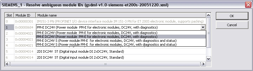
Note: Automatic creation of variables can be done primal after this step.
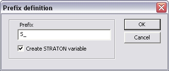
"Create variables for slave
modules"
Find this command in the context menu of the device. Based on the
defined device modules the referring variables are generated. You
can define a prefix for the variables to keep them unique.
“Create
slave diagnostics”:
Find this command in the context menu of the device. Based on the
Profinet standard the referring variables are generated. You can
define a prefix for the variables to keep them unique.
The following variables are
generated:
- CycleCounter [UINT]
- Status [BOOL]
- DataValid [BOOL]
- ProviderState [BOOL]
-
StationsProblemIndikator [BOOL]
“Create IOxS for slave
modules”
Find this command in the context menu
of the device. Based on the defined device modules the referring
IOPS- and IOCS-variables are generated. You can define a prefix for
the variables to keep them unique.