Kontron ThinkIO / Wago I/O System 758
The workbench offers a fully integrated Configurator for the Kontron ThinkIO / Wago I/O System 758. In the following this device will be called as ThinkIO. Please choose one of the following chapters for detailed information for using the ThinkIO:
Data exchange
Configuration
Data types
Additional features
Data exchange - Configuration:
The T5 Runtime manages the linking table which contains all Inputs and Outputs of the ThinkIO. A referring Configuration tool is integrated in the Workbench. To start it click "File / Open / Fieldbus Configuration" in the main window. A window for the fieldbus configuration will be opened. Click the tap "I/O driver". Choose "Edit / Insert configuration… ".
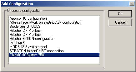
Choose the referring entry and click OK.
The configuration is set up as tree structure:
-
ThinkIO/IOSystem
758
- Areas
- Inputs/Outputs
- Variables
With"Edit / Insert Master/Port…" the basic structure of the ThinkIO will be set up.
With "Edit / Properties…" with selected entry "Areas" the following window will be shown:
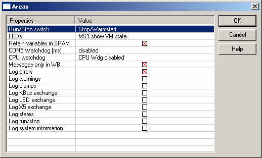
This settings can be done:
| Run/Stop switch |
Configuration of the Run/Stop switch:
Pause/Run: Position Stop stops the execution of the application. Run continues the execution (Hot Restart). Stop/Cold start. Position Stop stops the application. Run causes a cold restart. Stop/Warmstart: Position Stop stops the application. Run causes a warm restart (cold with retain variables).
If the Run/Stop switch is at Stop at Runtime start, the application won't be started. |
| LEDs |
Configuration of the LEDs of the ThinkIO:
As I/O: All LEDs can be used by the application. I/Os MS1 show VM state: MS1 shows the status of the Runtime, all other LEDs can be used by the application. LEDs not used: All LEDs are used by the system only. MS1 show VM state: MS1 shows the status of the Runtime. All other LEDs are used by the system.
Show VM State - in two modes the LED MS1 shows the status of the Runtime: - On: application running - Blink: application running, breakpoint set. - Off: application is stopped.
Address areas of the LEDs (Offset 0, Bit x): 0...STA (not accessible) 1...ERR (not accessible) 2...MS1 3...MS0 4...IO green 5...IO red 6...PWR 7...IDE |
| Retain variables in SRAM | When activated, the retain variables are stored in the SRAM (battery buffered RAM). When deactivated the retain variables are stored on the flash disk. |
| CON5 Watchdog [ms] |
The watchdog of the X5 plug is enabled/disabled here. If the watchdog is enabled once it can't be disabled any more. If the Runtime is stopped the whole system must be reseted due to watchdog timeout. A cycletime overflow causes a watchdog timeout as well. Available watchdog settings: disabled, 127, 508, 1016, 2033ms |
| CPU Watchdog | Enable/disable the CPU Watchdog. With this firmware version the CPU Watchdog cannot be used. |
| Messages only in WB | With this setting all messages will be sent to the Workbench. No local storing of log-files. This option is used to protect the flash disk from being overloaded. |
| Log errors | Error messages are logged |
| Log warnings | Warnings are logged |
| Log clamps | Logging of found K-Bus clamps |
| Log K-Bus exchange | Logging of K-Bus exchanges |
| Log LED exchange | Logging of LED exchanges |
| Log X5 exchange | Logging of X5 plug exchanges |
| Log states | Logging of ThinkIO states |
| Log run/stop | Logging of the run/stop switch |
| Log system information | Logging of ThinkIO specific information |
As visible in the tree structure the following areas can be configured:
| Locale inputs |
Both inputs of the X5 plug are supported. Create variables via context menu. |
| Local outputs |
Both outputs of the X5 plug are supported. Create variables via context menu. |
| LED |
The LEDs MS0, MS1, IO green, IO red, IDE und PWR can be used by the application. The availability of the variables depend on the settings made in the properties of "Areas". Via context menu the variables can be created. All LEDs are defined as variables. Un-allowed variables have to be removed manually! |
| K-Bus digital inputs |
This area represents the digital inputs relatively to the start of all digital inputs of the K-Bus. Digital inputs are stored separately to save time when adding new analog inputs! |
| K-Bus analog inputs | This area represents all inputs of the K-Bus with absolute offset. |
| K-Bus digital outputs |
This area represents the digital outputs relatively to the start of all digital outputs of the K-Bus. Digital outputs are stored separately to save time when adding new analog outputs! |
| K-Bus analog outputs | This area represents all outputs of the K-Bus with absolute offset. |
| States
(see "Additional features") |
This area gives information to the ThinkIO and the status of the K-Bus. Firmware: Identifier for firmware version. Fieldbus: Identifier for supported fieldbus systems. OEMVariant: Identifier for OEM variant. Battery: Condition of battery. Due to design error this value represents OK always. X5WdgFailed: TRUE if X5 plug watchdog timeout is active. BitlengthKBus: Size of image on K-Bus [bit]. NrClamps: Number of clamps on K-Bus. ErrorType: Type or error on K-Bus. ErrorArgument: Error specific error code. NrClampsWithError: Number of defective clamps on K-Bus. LedError: LED error active. LedErrorArgument: Additional information regarding LedError. CfgNoClamps: Number of detected clamps on K-Bus. PosClampX: Position of image for clamp X on K-Bus. TypeClampX: Identifier for type of clamp on K-Bus. SizeClampX: Length of data for clamp X on K-Bus. |
Use "Edit / Insert variable…" to create a variable in the chosen area.
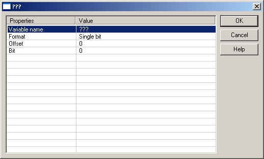
The following entries can be done:
| Variable name | |
| Format | 32 bit float, Boolean Byte, Signed 16 bit integer, Signed 32 bit integer, Signed 8 bit integer, Single bit, Unsigned 16 bit integer, Unsigned 32 bit integer, Unsigned 8 bit integer |
| Offset | |
| Bit |
Note: The offset is relative. So the offset for the first variable is always 0.
All settings can also be done in the Grid. Click "View / Grid" to switch on/off the grid. The listed information always refers to the items selected in the tree.
The grid show online values of the Runtime if the Workbench is online.
You can freely map a variable of any data type to an I/O. The runtime automatically converts the value to the type of the variable. STRING variables are not supported.
“Create all
default variables”:
This command is available in the context menu of the item "Areas"
in the tree. With that all default variables for the ThinkIO will
be created.
Choose the needed default variables.
Clamp information: K-Bus clamp status for X clamps
Device information: information of the device
ThinkIO health state: states of the device
Default variables can be created Area-sensitive:
“Create variables for local inputs”:
Creates both input variables of the X5 plug.
“Create variables for local outputs”:
Creates both output variables of the X5 plug.
“Create LED variables”:
Creates variables for the ThinkIO LEDs.
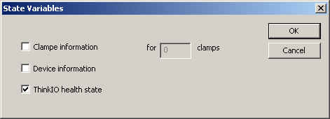
“Create state variables”:
Creates state variables after the selection.
Possible selections:

Clamp information: K-Bus clamp status for X clamps
Device information: information of the device
ThinkIO health state: states of the device