Step 12 - Switching points used in the Hall schedule |
|
Manual -> Production and Facility Scheduler (PFS) -> Configuring objects with the Production & Facility Scheduler -> Step 12 - Switching points used in the Hall schedule |
|
|
Step 12 - Switching points used in the Hall schedule |
|
Manual -> Production and Facility Scheduler (PFS) -> Configuring objects with the Production & Facility Scheduler -> Step 12 - Switching points used in the Hall schedule |
|
|
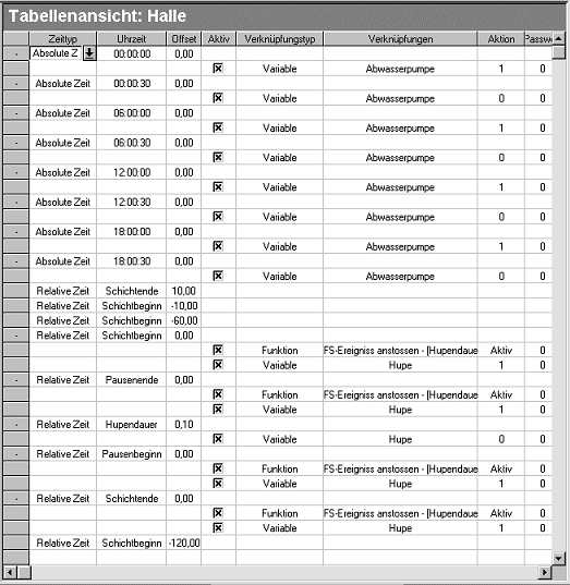
We have used times to define moments at which events are executed, and must now define what will actually happen at the specified time. This is what switching times are used for.
Let us begin with the waste water pump. Select
the absolute time 00:00:00.
In the context neu click the entry Create switching point. A new line is
added just after the selected time; this line represents the
switching point. Switching points contain the following columns:
Active, Type of link, Links, Action and Password. Let us take a
quick look at these fields.
Active: This field enables you to deactivate a switching point. You can use it to block a switching point's execution.
Type of link: This field specifies if a variable must be modified, for instance, or if a function must be performed. The other types of links are broached in the Switching point object section.
Links: According to the selected type of link, this field enables users to select the required variable or function.
Action: When the Variable link type is selected, this field contains the set value which must be written. When dealing with functions, this field is just as important as the Active field.
Password: Enables specific permissions to be requested for the configuration of the Runtime environment.
We shall now proceed to define the switching
point. The currently selected column is Type of link. Select the item
Variable from the list box.
Now, change to the column Links. Select the Waste water pump from the list box.
Now, change over to the column Action. In this column, specify a value
of "1". This means that at 00:00:00, the set value will be set to 1
for the Waste water pump variable.
Now, create the following switching points, proceeding as described above:
|
00:00:30 Variable: Waste water pump; Set value: 0 |
|
06:00:00 Variable: Waste water pump; Set value: 1 |
|
06:00:30 Variable: Waste water pump; Set value: 0 |
|
12:00:00 Variable: Waste water pump; Set value: 1 |
|
12:00:30 Variable: Waste water pump; Set value: 0 |
|
18:00:30 Variable: Waste water pump; Set value: 1 |
|
18:00:30 Variable: Waste water pump; Set value: 0 |
We shall now deal with the horn. As you recall,
we have defined a number of relative times for the horn.
Shift start offset 0, Shift end offset 0, Break start offset 0,
Break end offset 0 and Horn Tone offset 0,1.
Two switching points must be executed for the horn tone start and
end, respectively. The first switching point activates the horn.
The second switching point triggers the user event Horn Tone.
The relative time Horn Tone
must then deactivate the horn. So, let us proceed to create the
required switching points. Unlike the waste water pump
configuration above, this configuration uses 4 different times,
thus requiring several switching points. For instance, for the time
Shift start offset 0 we
could activate the Create switching points function twice
consecutively. However, a more convenient solution is provided. To
do this select the time Shift
start Offset 0. In the context menu activate Add switching points. The program now
displays the Create switching points dialog. Select the function
PFS Event [Horn Tone] and
the variable Horn. Then
click on Add to effectively
add these to the results list. After you have clicked on
OK, two switching points
using the relevant Type and Link parameters will be created. You
must still set the set value to 1 for the switching point variable
Horn. Now, use the same
method to define the switching points for the relative times Shift
end, Break start and Break end. We shall now create the final
switching point for the horn by defining for the relative time
Horn tone a switching point
which will sets the variable Horn to 0.

|
|
|
A decimal value can be entered with a colon as well as with a point, the decimal point will automatically be changed to a point. |