|
Dial-up networking and Citect
Technical Paper
August 2004
AbstractThis paper presents details on dial-up networking and CitectSCADA versions 5.2x, 5.3x, 5.4x, 5.5x and 6.xx
Contactssupport@citect.com ContentsIntroduction
Introduction
Although this is a guideline on how to configure Dial-Up Networking for use with Citect, it is highly recommended that you have a solid understanding of navigating through your Operating System, an understanding of the Citect System and a basic understanding of Networking. Before reading any further, also make sure that you have at least Power User privileges, or even better Administrative privileges on both the machines that you will be configuring. If uncertain, please contact your IT department or Network Administrator to configure your Dial-Up networking for you.
|
|||||||||||||||||||||||||||||||||


|
Figure 1.0 |
With this method, you have a Citect Server, which has a modem connected to it, with a modem connected directly to it, this will act as the Dial-Up server for Display Client / Internet Display Client. It is essential that with the increased amount of security introduced in Windows 2000 and Windows XP, you are aware of User Account Types and Dial-Up Account settings. If uncertain, please consult with your IT or Network Administrator. You can also read upon Network Security in a lot more detail simply by getting on the internet and searching for relevant information. The Microsoft Knowledge Base (www.microsoft.com) should be sufficient for this type of information.
Advanced Method
The Advanced Method will be ideal for medium to large size networks. If using this type of method, it is important that you check with Company Network Policies on whether they allow Dial-Up connections to site. Although we are not tunnelling through to the LAN in a Virtual Private Network (VPN) method, it is still important to get approval, or the assistance of the IT or Network Administrators on site, before going ahead with this. With this Advanced Method, we will already have a larger Citect Network established, which may be part of an existing LAN, with its own LAN server or servers for both the Citect Network and the Company Network (see Figure 2.0).
|
Figure 2.0 |
With the Advanced Method the LAN Server will act as the Dial-Up Server and will route the information from the Citect Server through to the Dial-Up Display Client / Internet Display Client. The actual Citect configuration will be no different in this scenario, however it is still regarded as a more Advanced Setup as the LAN Server may impose possible security restrictions. If possible, I would recommend the Simple Method is applied to this also. That is, instead of having the Modem connected to the LAN Server, you simply plug it to the Citect Server and establish a direct Dial-Up link with the Citect Server and Display Client / Internet Display Client, bypassing the LAN server entirely (see Figure 2.1)

|
Figure 2.1 |
Configuration
Now that you have read through and understood some of the settings required, we can move onto configuring the Server and Client step-by-step. First we will configure the Servers Dial-Up, and then we will configure the Clients Dial-Up. We will then proceed to test the communications simply by transferring a text file between the two. Once we can confirm that the connection is reliable, and the text file has transferred across, we will then configure the Citect Server and the Citect Display Client / Internet Display Client.
Now that you have read through and understood some of the settings required, we can move onto configuring the Server and Client step-by-step. First we will configure the Servers Dial-Up, and then we will configure the Clients Dial-Up. We will then proceed to test the communications simply by transferring a text file between the two. Once we can confirm that the connection is reliable, and the text file has transferred across, we will then configure the Citect Server and the Citect Display Client / Internet Display Client.Modem Configuration
Before we setup our Dial Up networking on either end, it is important to connect our modem, and run a brief test on them to make sure they are functioning. Please consult your Modem Owners manual on how to install your modem. Once the modem is installed, follow the steps provided below to confirm that it is functioning.
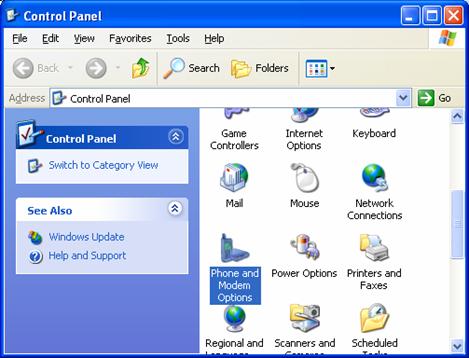
- Go into Windows Control Panel and double click “Phone and Modem Options”
- In Phone and Modem Options, Click on the “ MODEM ” tab select the “Installed Modem” that you will use for your Dial Up networking, and Click on the “Properties” button to go into the Modem Properties Window.

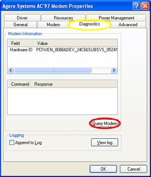
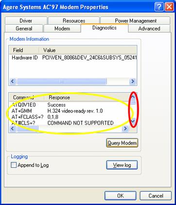
- You should now see the Modem Properties Window. In here you will need to click on the “ Diagnostics ” tab, and then click on “Query Modem”. This will Query the modem and come back with Diagnostics information on the modem.
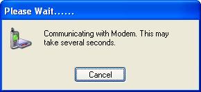
- You will initially see a “Please Wait…..” status window.
This will then place you back in the Diagnostics window. This time you will see “diagnostic data” in the lower half of the window. You should use the “scroll bar” and go through the list of responses that have come through. Make sure that none of them are marked as “FAILED”. If so, you will need to consult your modem manual to diagnose the fault. Once the fault is resolved, continue on to the next step.
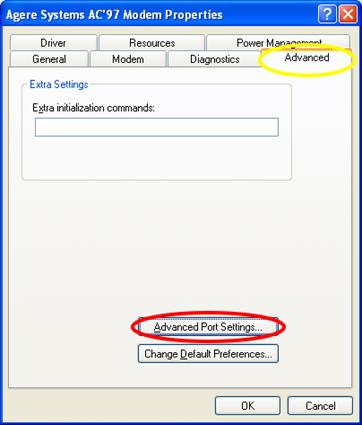
- Since you are still in the modem properties window it is worth while to make one final adjustment. Click on the “ Advanced ” Tab, then click on “Advanced Port Settings”
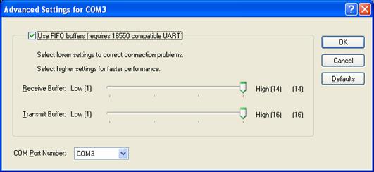
- You will see the “Advanced Port Settings” window, make sure that the Transmit and Receive Buffers are set to high. This will ensure that you have a large buffer size for data, which improves performance . With slower modems, it is good practice to decrease these settings, to correct generic connection problems. Click on OK to confirm changes and continue clicking on OK to exit out of the modem properties
- Now you have successfully setup your modem and it is ready for use. Simply exit out of the Modem Properties window and remember to repeat the procedure on your Client machine.
Dial Up Server Configuration
An assumption that is made before we go any further is that you are utilising a standard MODEM and not one that supports simultaneous Dial Up connections by having multiple telephone lines running into it. Please make sure that you are logged on your Windows system as an Administrator or Power User, other wise you will not have access to the following configuration windows.
Having confirmed that your MODEM is correctly configured to use with your machine, it is time to utilise it by setting up your Server to allow Dial Up connections to be made to it. Under Windows XP and Windows 2000, this is known as “Incoming Connections”. Follow the steps provided below to configure this.
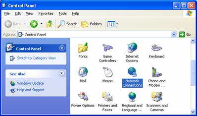
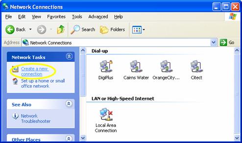
- Go into Windows Control Panel and Select “Network Connections”
-
Once you are in the Network Connections window you will need to click on “create a new connection”.
 >
> -
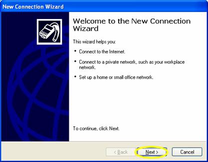
This will start the New Connection Wizard click next to continue on to creating a new network connection.
-
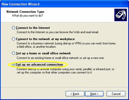
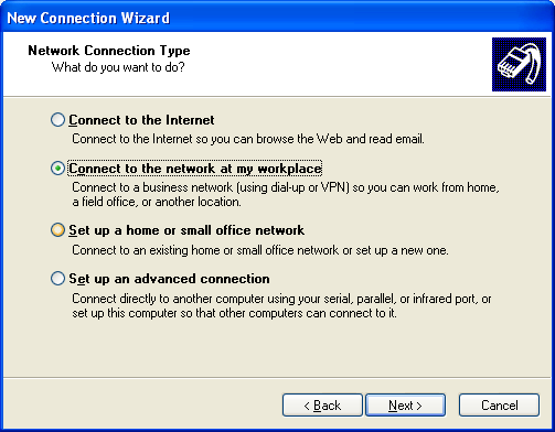
This will now bring you to the next section, choosing a type of connection you will be creating. Here you will need to select “Set up an advanced connection” then click next to continue.
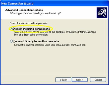
- Here you need to select “Accept Incoming Connections” and click
on next to continue
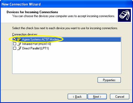
- This will now ask you for the device to use for the incoming
connection type. Here you will select the modem that you have
installed previously. Once you have selected it click next to
continue.
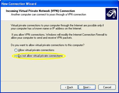
- Here it prompts you to allow or disallow a VPN through this
incoming connection. If uncertain, please consult your Network or
IT Administrator. This feature is not necessary for setting up
Citect, therefore we will choose “Do not allow virtual private
connections” and click on next to continue.
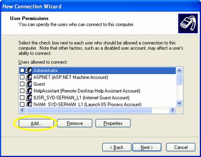
- This is where you are be asked to configure users for this
connection. Click on “Add” to create a new user.
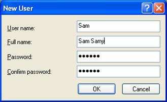
- The Add User window will pop up asking you to add a user name,
the full name, a password and to confirm the password. In this
example I have used Sam as the password, placed Sam Samy as the
full name and Citect as the password. Please do not forget this
password as you will need to use it later on. Click on OK to
continue. NOTE: The passwords are Case Sensitive
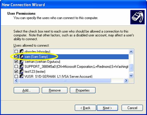
- If you have added the New User correctly, you should see the
“User Name” appear in the list, try scrolling through until you see
it. If not there repeat step 9. If you are going to have multiple
Dial Up users, you can either use a generic User Name and password
that you can distribute to all of them, or create individual
accounts for each one of them. This is achieved by adding more
users and placing tick marks next to their names. This will allow
you to keep track of them through log files under Windows XP / 2000
and see who was logged on and at what times. Click next to
continue.
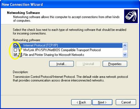
- Now you are asked to select protocols and services that you
would like to use for this connection. These will all be usually
selected for you by default, however if not, confirm that TCP/IP is
selected and click next to continue.
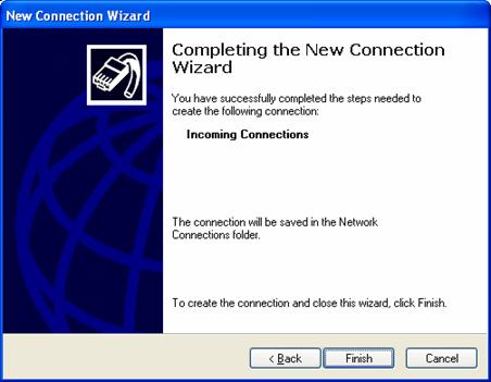
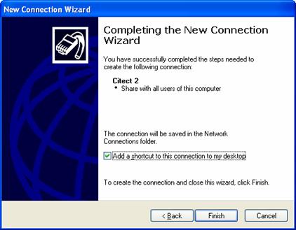
- You have now completed setting up your incoming connection,
click on Finish to finalise this.
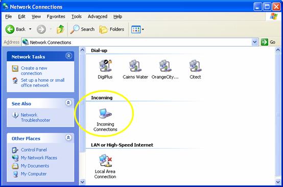
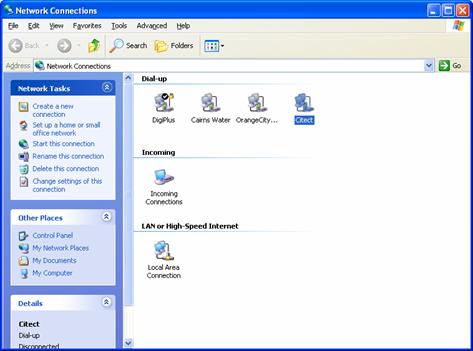
- You will now see the newly configured connection under the
“Network Connections” window.
Dial Up Client Configuration
Please make sure that you are logged on your Windows system as an Administrator or Power User, other wise you will not have access to the following configuration windows. Having confirmed that your MODEM is correctly configured to use with your machine, it is time to utilise it by setting up your client to Dial out to the server that you have previously configured.
Follow the steps provided below to configure this.
- Go into Windows Control Panel and Select “Network Connections”

-
Once you are in the Network Connections window you will need to click on “create a new connection”.
-
This will start the New Connection Wizard click next to continue on to creating a new network connection.

-
This will now bring you to the next section, choosing a type of connection you will be creating. Here you will need to select “Connect to the network at my work place” then click next to continue.
-
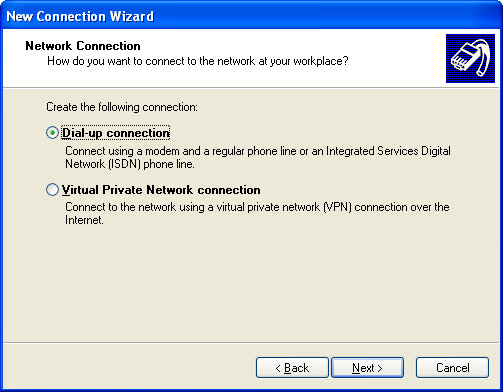
In the next “Network Connection” window make sure you select the “Dial Up connection” and click on next to continue.
-
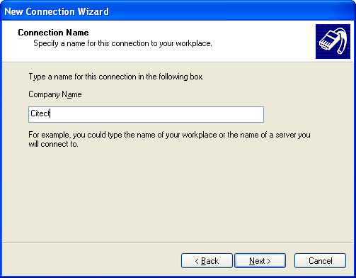
In this new window you will be prompted to give the connection you are using a name, using logical names is advised here, especially if you are going to setup multiple connections to different dial-up servers at a later stage. Examples of logical names are “Sinter Plant”, “East Wing”, “Leichardt Water Tower”, etc etc.
-
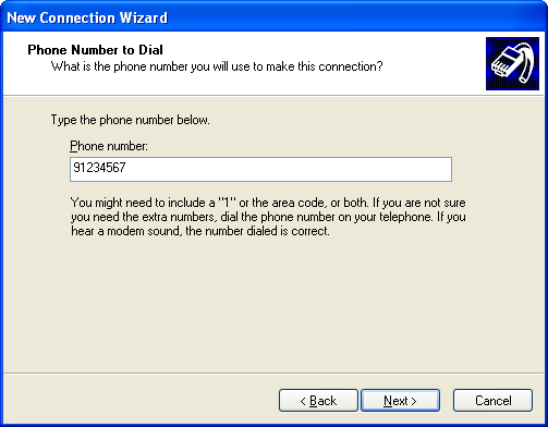
This next window will prompt you for the telephone number that you are going to dial. This is the telephone number that your Servers modem is connected too.
-
Congratulations, your dial up connection is now complete. Here you have the option of “Add a shortcut to this connection on my desktop” where you can conveniently access the dial up by double clicking its shortcut icon.
Dial Up Confirmation
Now that you have completed the configuration of your dial up server and dial up client, it is advised that you test it out to confirm that it works. Some notes to consider prior to testing.
- Make sure that both your Server and Client machines are physically connected to the phone line
- Make sure that if using external modems that they are powered on with no error signals.
- Make sure that you are logged on to both the machines with the right level of privileges to make outgoing calls.
Once you confirm that everything is in order, and then follow the rest of the instructions below.
- Simply double click the shortcut on the client machine that will establish the connection for you. (Alternatively you can browse into the Network Connections folder and double click on the Dial-Up shortcut in there.
- This will bring up a dial up window that will prompt you for a user name and password. This is the same user name and password that you have defined in Section 9 of the “Dial Up Server Configuration”.
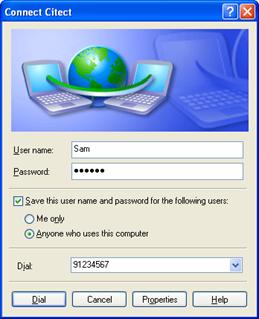
- Once you’ve typed in your user name and password, you can choose to save the user name and password, and have it set so that any one using the client pc can also use it to dial out with, or it is only restricted to “Me Only” which is the currently logged on user.
- Click on Dial and wait for it to establish a connection.
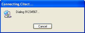
- Once the connection is established, you should see it minimise down to your system tray and you will notice an animation where the icon will be flashing .

Citect Server Configuration
Now that you have completed the setup of your Dial-Up networking with windows, it is advised that you do a basic test where you dial in to your s.
Citect Client Configuration
Ci Client info here
The nittty gritty bits
Tools / Documents required
- MS utility lanacfg.exe (See more on Lanacfg for instructions on using this)
- MS KB138037 “ http://support.microsoft.com/default.aspx?scid=kb;en-us;138037 ” article below for information on What LANA is and how it is implemented.
- Citect KB article Q2173, also added below.
- For those of you using Windows NT and Windows 2000 (eg Client is Win2K and Server is WinNT), the LANA number can be found in the following way
I. Log in as administrator
II. Open Properties of Network Neighborhood
(or open the Control Panel/ Network applet).
III. Click the Services Tab.
IV. Click on NetBIOS Interface
V. Click the Properties Button. Your LAN
number should be here.
Note: Dial up adapters are set up in windows by using the Windows 2000 wizard.
LANACFG is part of Windows NT, however it is not part of Windows
2000. You can find this as an Add-on tool on the Microsoft website
http://corporate.windowsupdate.microsoft.com/
To correctly setup and utilise LANA on a PC, the concept must first
be understood, thus the reason MS KB138037 is referenced here at
this point in time.
Dial in Server:
Dial in to the server from the remote dial in client, you can
monitor the status of the connection and view the details of
interest;
That is, speed/transport/authentication/server and client IP
addresses.
After a successful dial in, run the IPConfig utility in a command window, you should see both your SCADA lan adapter and your dial in adapter;
Windows 2000 IP Configuration
Ethernet adapter Local Area Connection:
Connection-specific DNS Suffix . :
syd.cit.com.au
IP Address. . . . . . . . . . . . :
192.168.0.26
Subnet Mask . . . . . . . . . . . :
255.255.254.0
Default Gateway . . . . . . . . . :
192.168.1.254
PPP adapter RAS Server (Dial In) Interface:
Connection-specific DNS Suffix .
:
IP Address. . . . . . . . . . . . :
192.168.0.140
Subnet Mask . . . . . . . . . . . :
255.255.255.255
Default Gateway . . . . . . . . . :
For the sake of clarity I have only shown one of each adapter, this will show you the IP address assigned to the WAN or PPP adapter.
Dial in Client:
After a successful dial in, run the following in a command box; Nbtstat –s
Local Area Connection 5:
Node IpAddress: [169.254.244.96] Scope Id: []
NetBIOS Connection Table
| Local Name | State | In/Out | Remote Host | Input | Output |
| ---------------------------- | ------------ | -------- | ---------------- | ------- | --------- |
| DANIELSTRAND <03> | Listening | ||||
| DANIELSTRAND$ <03> | Listening | ||||
| JOEHABERBUSCH <03> | Listening |
\Device\NetBT_Tcpip_{AE1DD596-FCB1-4213-96C0-CCE46E53E B07 }:
Node IpAddress: [192.168.0.19] Scope Id: []
No Connections
The bottom line will show you the adapter ID, the number in the “ {} “ brackets. You will also notice that this matches up with the IP address from the client as shown in the status dialog box above.
We need to match this up with the Lan adapter number on the client that is bound to this WAN or PPP adapter. We can do this by running the MS utility Lanacfg.exe. The command line is;
C:\> lanacfg showlandiag
NetBios Bindings and Lana Information -------------------------------------
Lana: 9 Export: 1 Path:
\Device\Nbf_{8C220BCA-E297-4A4C-ABFF-0F69EBDF2E6D}
Lana: 6 Export: 0 Path:
\Device\NetBT_Tcpip_{AE1DD596-FCB1-4213-96C0-CCE46E53E B07 }
Lana: 4 Export: 1 Path: \Device\NwlnkNb
Maximum Lana: 22
I have only shown 3 lana number for the sake of clarity, on my notebook I actually had 22. You will see more information like RPC information also. The important thing is to find the lan adapter that has the same ID as the one being used in the NETBIOS table above. In this example it is Lana: 6.
In the citect.ini file of the client we have to then specify this lana number for citect to use,
[lan]
disable=0
groupname=0
lana=6
The above are the important parameters for dial in networking in Windows2000.
LMHOST Settings
Note: The LMHost entries need only include machines which are on an other subnet. This is because the TCP/IP driver isues a b-node request (i.e. broadcast requsting the IP address given the NETBIOS name) within the subnet.
The nbtsta t utility can be used to re-load the LMHosts file into cache without re-starting Windows. ie
nbtstat -R reloads the remote cache name table
nbtstat -r lists the contents of the cache
IP Forwarding
TCP/IP) forwarding is disabled by default in Windows 2000. To enable TCP/IP Forwarding
- Use Registry Editor (Regedt32.exe) to view the following registry key: HKEY_LOCAL_MACHINE\SYSTEM\CurrentControlSet\Services\Tcpip\Parameters
- Set the following registry value:
Value Name: IPEnableRouter
Value type: REG_DWORD
Value Data: 1
A value of 1 enables TCP/IP forwarding for all network connections installed and used by this computer.
Multi Homing
If you intend to use multiple network adapters in your Citect machines then we will need to set up one machine to act as a router. To date this has not been successful and it is a method that we will avoid at this point in time, till further investigation is conducted to find out the reasoning behind it.
Final Notes
With all this now accomplished, simply make sure that the server computers local hard drives can be browsed from your dial in client. Pinging the Server does not necessarily mean that you have gained access to the machines resources, but simply created a connection between your dial-up machine and the server. Once you have completed this, then you are ready to install your citect project and have it up and running. Additionally please remember to make sure that you have the latest Dongle Drivers available to use on your machine. You can download the latest driver from www.rainbow.com .
How do I setup Citect to run across the Internet?
Article number: Q2173
Updated on: 19/12/2001
For Citect versions: x.x
Summary
How do I setup Citect to run across the Internet?
Solution
First thing to keep in mind is that the Internet is no different
from any other TCP/IP Network except that it is bigger.
Imagine that we have Citect Server located in Sydney, Australia (IP address: 203.19.130.13) and that we want to connect to it with a Display Client in New York (IP address: 201.11.135.3). When the Display Client starts up you will see in the startup popup dialog how Citect is "Calling 'IOServer' ", "Calling CitectTrend", "Calling CitectAlarm" and finally "Calling CitectReport". What actually happens now is that Citect tries to establish a direct contact with the server but this will fail as NetBIOS will try to do a broadcast and only TCP/IP does not allow NetBIOS to make a broadcast on the Internet. Therefore we have to help TCP/IP find the Citect server without doing a broadcast on the network. This is done by a LMHOSTS file. This file has a simple structure which enables TCP/IP to look up a computer name and get its IP-address to establish a connection. The structure of the LMHOSTS file is as follows:
<IP-address> <computer name> #PRE
To setup the above example follow these steps:
- Setup the Sydney server with the Computer Setup Tool as a Networked Server and Display Client and the Display Client in NewYork as a Networked Display Client, also manually change the parameter [CLIENT]Display=1.
- Make sure that the Citect server can be reached from the Display Client with the PING command. Type PING 203.19.130.13 (exchange this address for your server address) from the MS-DOS prompt on the Display Client. If you get no response you have to check your Internet connection from both your computers.
- Edit the LMHOSTS file on the Display Client.
In our above example the Display Clients LMHOSTS file should look as follows:
203.19.130.13 IOServer #PRE
203.19.130.13 CitectAlarm #PRE
203.19.130.13 CitectTrend #PRE
203.19.130.13 CitectReport #PRE
Use a text editor to create a file as above or edit the default file called LMHOSTS.SAM and save it as LMHOSTS (note! the name of the file is LMHOSTS. with no extension).
The LMHOSTS file resides:
Window95: \WINDOWS
Windows NT: \WINNT\SYSTEM32\DRIVERS\ETC.
- Modify Citect.ini file on the display client as follows:
under [lan] add these two lines NetBIOS=0; TCPIP=1.
Under [DNS] add or change this line primary=, to Primary =aaa.bbb.ccc.ddd
(the IP address of server)
- Then modify Citect.ini file on the server as follows:
under [lan] add TCPIP=1.
- Restart your Display Client and make sure you are connected to the Internet.
- Start up your application on the Display Client. You should now see how the Client connects to the server across the Internet
Author: Daniel Strand
More on LANACFG.EXE
The LANACFG.EXE should be placed into the WINNT\SYSTEM32 folder. The installer usually will do this for you. Your next step in running this is to get into the Command prompt. This can be done by clicking on the “START” button and clicking on Run. Run will bring up a dialog where you can type in “COMMAND” and press OK
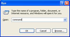
Now you should see a window similar to the one below:
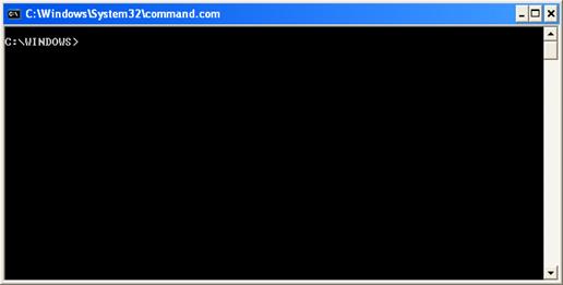
Type in lanacfg with no parameters, you will be presented with 4 command line options to use.
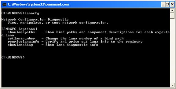
The above parameters better explained below:
showlanapaths - Show bind paths and
component descriptions for each exported lana
setlananumber - Change the lana number of a
bind path
rewritelanainfo - Verify and write out lana
info to the registry
showlanadiag - Show lana diagnostic
info
If you run "lanacfg showlanapaths", the LANA number information will display to the screen. However if you run "lanacfg showlanapath>lanaconfig.txt", a text file called lanaconfig.txt will be created with the same information. The 'lanacfg showlanapaths' will basically give you a list of what LANA numbers are configured, and where they go.
The output will look something like:
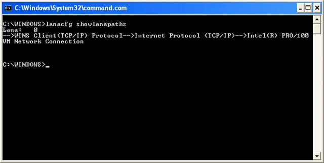
In this example, there is only 1 LANA numbers, number 0 going
through TCP/IP.
In some networks, there maybe a large number of LANA numbers, each
assigned through to the different protocols currently being used on
that machine, and this gets more complex if you have more than one
network interface card in the PC.
HOWTO: Use LANA Numbers in a 32-bit Environment
The information in this article applies to:
Microsoft Windows 2000 Server
Microsoft Windows 2000 Advanced Server
Microsoft Windows 2000 Professional
Microsoft Win32 Software Development Kit (SDK) 3.1
Microsoft Win32 Software Development Kit (SDK) 3.5
Microsoft Win32 Software Development Kit (SDK) 3.51
Microsoft Win32 Software Development Kit (SDK) 4.0
This article was previously published under Q2173
SUMMARY
NetBIOS uses the concept of a LANA (LAN adapter number) that allows you to write transport-independent NetBIOS applications. This article describes what a LANA is and recommends an approach to writing NetBIOS applications.
MORE INFORMATION
A LANA is a field of the NetBIOS NCB structure. In IBM's NetBIOS
3.0 specification, a LANA was used to specify a particular network
adapter, as NetBIOS then supported up to two network adapters in
one PC computer. Specifying a LANA of zero directed a request to
the first adapter, and specifying a LANA of one directed a request
to the second adapter.
Originally, IBM sent NetBIOS packets over the NETBEUI protocol,
also known as the NetBIOS Frames protocol. This was the only
transport NetBIOS could use to send data across the network. In
other words, each network adapter had only one protocol to send and
receive NetBIOS packets.
Because most computers have only one network adapter, many
MS-DOS-based applications send all their requests to a LANA value
of zero (also called simply 'LANA zero'). If a second network
adapter is installed, some programs allow the user to configure the
application to use LANA one instead. As a result, LANA zero became
a default setting, though it was never intended to be a
default.
Today's network technology allows NetBIOS to use transports other
than NETBEUI. Microsoft has extended the meaning of LANA to
indicate a specific transport on a specific adapter. For example,
if you have two network adapters, and have IPX/SPX and NETBEUI
transports installed, you have four LANAs. The LANAs may or may not
be sequential, and there is no systematic way to identify which
transport maps to which LANA.
In addition to extending the meaning of a LANA, Microsoft also
added an NCB command (NCBENUM) that returns an array of available
LANA numbers. As an example, the LANA_ENUM structure filled by
NCBENUM might hold an array with values 0, 3, 5, and 6. Zero might
map to IPX/SPX on the first adapter, three might map to NETBEUI on
a second adapter, and so on.
In Microsoft Windows NT, Windows 2000, Windows 98, and Windows 95,
network adapters consist of physical adapters (like a 3Com
Etherlink II) and software adapters (like the Dial Up Adapter). In
addition, a user may have TCP/IP, NETBEUI, IPX/SPX, and other
transports installed, all of which have NetBIOS support.
For Windows NT, LANAs are configurable through the control panel.
Choose the Network applet, choose the NetBIOS Interface component,
then choose Configure. A dialog appears that allows you to edit the
LANAs.
For Windows 2000, there is no user interface element to configure
LANA numbers; the system assigns the LANAs automatically.
The LANACFG.EXE command line utility is used to view and configure
LANA's. This utility is available for download at the following Web
site: http://corporate.windowsupdate.microsoft.com/
For Windows 95, you may only set LANA zero, the default
protocol, and if no protocol is set as default, there won't be a
LANA zero. You can set the default protocol in the control panel.
Choose the Network applet, choose the protocol you want as default,
choose Properties, the Advanced tab, and finally check 'Set this
protocol to be the default protocol'.
LANAs may seem like a constraint that your application must work
around. However, making your application ignorant of how users want
to configure their machines is a powerful idea, and one that makes
life easier for your customers.
The best way to write a NetBIOS application is to support all
LANAs, and establish connections over any LANA. A good approach is
outlined in the following steps:
1. Enumerate the LANAs by submitting NCBENUM.
2. Reset each LANA by submitting one NCBRESET per LANA.
3. Add your local NetBIOS name to each LANA. The name may be the same on each LANA.
4. Connect using any LANA:
For servers, submit an NCBLISTEN on each LANA. If necessary, cancel any outstanding listen after the first listen is satisfied.
For clients, submit an NCBFINDNAME (Windows NT only) or an NCBCALL (Windows NT, Windows 98, or Windows 95) on each LANA. The first successful find name or call will indicate which LANA to use. When using NCBCALL instead of NCBFINDNAME, you must cancel any pending NCBCALLs and hang up the extra completed calls (when two or more calls are successful.)
It is a good idea to submit NCBADDNAME, NCBLISTEN, NCBFINDNAME,
and NCBCALL asynchronously. Asynchronous requests will be processed
almost in parallel on each transport.
This architecture is quite beneficial. Once your application is
written to establish connections in this manner, it will support
any transport that NetBIOS can use. As a result, your customers
will not have to configure anything within your application, and
your application will not be affected by dynamic LANAs such as
dial-up adapters or plug-and-play hardware.
REFERENCES
IBM NetBIOS specification version 3.0 and Win32 SDK Documentation.
Microsoft Knowledge Base Article – 158781
Determining LANA Numbers in Windows 95
Applies To
This article was previously published under Q2173
SUMMARY
To determine which LANA numbers are being used on a Windows 95
client, type net diag /status at a command prompt. The resulting
prompt asks you to enter the remote computer's NetBIOS name, or to
press ENTER to examine a local adapter's status. It then prompts
you to select the LANA number you want to use.
NOTE: You are prompted for a LANA number to use only if you are
using more than one protocol.
MORE INFORMATION
A NetBIOS-providing protocol set to be the default protocol is set to LANA 0. To find out which protocol is on which LANA, check the following registry key: HKEY_LOCAL_MACHINE\System\CurrentControlSet\Services\Class\NetTrans
Beneath this key is a series of \000x branches corresponding to the network protocols installed. Skipping the NetBIOS-providing protocol set as the default protocol, find the NetBIOS protocols being used and number their LANA numbers backwards from seven.
Examples
A Windows 95-based computer is using NetBIOS over IPX, TCP/IP, and NetBEUI. All three are NetBIOS providers. NetBEUI has been set as the default protocol. The NET DIAG /STATUS command shows:
Please enter remote computer's NetBIOS name, or
press ENTER to examine a local adapter's status.
Please enter the LANA number you wish to use. Choose from the
following NetBIOS-providing LANA(s): 0 6 7
The registry shows:
HKEY_LOCAL_MACHINE \System \CurrentControlSet \Services \Class
\NetTrans \0000 - IPX/SPX \0001 - NetBEUI \0002 - TCP/IP \0003 -
NetBIOS over IPX Using the above guidelines, you can determine
that:
NetBEUI is on LANA 0 (default protocol)
NetBIOS over TCP/IP is on LANA 7
NetBIOS over IPX is on LANA 6
Note that IPX/SPX is skipped because it is not a NetBIOS-providing protocol. Had NetBEUI not been set to be the default protocol, the NET DIAG /STATUS command would not have listed LANA 0:
Please enter the LANA number you wish to use. Choose from the following NetBIOS-providing LANA(s): 6 7
In this case, LANA numbers 6 and 7 are being used, and no NetBIOS- providing protocol has been set as the default protocol. Otherwise, the display would show LANA 0 being used
Disclaimer
Disclaimer of All
Warranties
SCHNEIDER ELECTRIC (AUSTRALIA) PTY LTD DISCLAIMS ANY AND ALL
WARRANTIES WITH RESPECT TO SCHNEIDER ELECTRIC (AUSTRALIA) PTY LTD
PRODUCTS AND THE RELATED DOCUMENTATION, WHETHER EXPRESS OR IMPLIED,
INCLUDING SPECIFICALLY THE IMPLIED WARRANTIES OF MERCHANTABILITY
AND FITNESS FOR A GENERAL OR PARTICULAR PURPOSE. CITECTSCADA AND
THE RELATED DOCUMENTATION ARE PROVIDED "AS IS," AND YOUR COMPANY
UNDERSTANDS THAT IT ASSUMES ALL RISKS OF THEIR USE, QUALITY, AND
PERFORMANCE.
Disclaimer of
Liability
YOUR COMPANY AGREES AND ACKNOWLEDGES THAT SCHNEIDER ELECTRIC
(AUSTRALIA) PTY LTD SHALL HAVE NO LIABILITY WHATSOEVER TO YOUR
COMPANY FOR ANY PROBLEMS IN OR CAUSED BY SCHNEIDER ELECTRIC
(AUSTRALIA) PTY LTD PRODUCTS OR THE RELATED DOCUMENTATION, WHETHER
DIRECT, INDIRECT, INCIDENTAL, SPECIAL, OR CONSEQUENTIAL (INCLUDING
LOSS OF PROFITS).
|
|
Related Links
Attachments