
WebClient across LAN / WAN - v7.0
Technical Paper

Abstract
This paper shows how to run both WebClient across LAN / WAN - v7.0
Setting up a LAN router to accept WAN Web Clients - v7.0
Note: It can be considered a security risk to open your SCADA Network to the Internet, or even the Corporate Network. In such environments, it is our advice to use third-party VPN software to allow external clients to securely and temporarily connect to the SCADA Network, then run the Web Client as a local LAN user, with default settings.
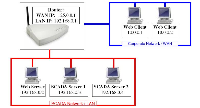
A Web Client can be located outside of the Local Area Network (LAN) to which both the Citect SCADA and Web servers are located. The setup shown above consists of redundant I/O, Report, Alarm and Trend Servers in a single ‘Cluster’.
Allowing Web Clients on the WAN to communicate to the SCADA Servers on the LAN, is a two-step procedure:
- Configure ‘Port Forwarding’ in the Router, so that requests to the ports of 125.0.0.1 are redirected to the appropriate Web / SCADA Servers.
- Configure ‘Address Forwarding’ so that the Web Clients knows to use these new addresses, instead of those configured in the project.
The following table defines the default ports for Citect v7.0, and those required for a Web Client to communicate with the SCADA and Web Servers, are highlighted in RED:
|
Default Port |
Server Type |
Server Role |
|
21 |
FTP Server |
Page downloads for IDC |
|
80 |
Web Server |
Project files for Web Client |
|
2073 |
CTAPI |
CTAPI Communications |
|
2074 |
Client |
Cicode Debugging |
|
2075 |
Report Server |
Report Server comms |
|
2076 |
Alarm Server |
Alarm Server comms |
|
2077 |
Trend Server |
Trend Server comms |
|
2078 |
I/O Server |
Legacy I/O Comms |
|
2079 |
IDC |
Internet Display Server/Client comms |
|
2080 |
Alarm Server |
Alarm Properties Connector |
|
2081 |
Time Server |
Time Server commns |
|
2082 |
I/O Server |
Publish Subscribe I/O Server Commns |
|
20222 |
ODBC |
ODBC Server |
Port Forwarding:
If your router has an inbuilt firewall blocking incoming communication, you must make sure that you define the above port numbers on the exclusion list to allow communication between client and servers.
For our example, you will then need to configure ‘Port Forwarding’ in your Router as follows:
|
Incoming IP:Port |
Outgoing IP:Port |
Server Type |
|
125.0.0.1:80 |
192.168.0.2:80 |
Web Server |
|
|
|
|
|
125.0.0.1:2075 |
192.168.0.3:2075 |
Report Server 1 |
|
125.0.0.1:2076 |
192.168.0.3:2076 |
Alarm Server 1 |
|
125.0.0.1:2077 |
192.168.0.3:2077 |
Trend Server 1 |
|
125.0.0.1:2078 |
192.168.0.3:2078 |
I/O Server 1 Peer Port |
|
125.0.0.1:2080 |
192.168.0.3:2080 |
Alarm Server 1 Properties Connector |
|
125.0.0.1:2082 |
192.168.0.3:2082 |
I/O Server 1 |
|
|
|
|
|
125.0.0.1:3075 |
192.168.0.4:2075 |
Report Server 2 |
|
125.0.0.1:3076 |
192.168.0.4:2076 |
Alarm Server 2 |
|
125.0.0.1:3077 |
192.168.0.4:2077 |
Trend Server 2 |
|
125.0.0.1:3078 |
192.168.0.4:2078 |
I/O Server 2 Peer Port |
|
125.0.0.1:3080 |
192.168.0.4:2080 |
Alarm Server 2 Properties Connector |
|
125.0.0.1:3082 |
192.168.0.4:2082 |
I/O Server 2 |
Note: For the Second I/O RAT Server, we cannot use the ports 125.0.0.1:2075->2082, as they have already been mapped to Server1. Hence, we must then use a different range of external ports, but we can still map them to the standard ports on the Servers, since the Servers are at different IP addresses.
i.e 125.0.0.1:3082 is mapped to 192.168.0.4:2080
Not having to change the ports on the Servers allows us not to disturb any configuration of existing Display Clients on the SCADA Network.
When connecting, the Web Client will use the WAN IP Address of the Router, 125.0.0.1. Internet Explorer uses port 80 as the default, so the port can be omitted. i.e:
http://125.0.0.1/Citect
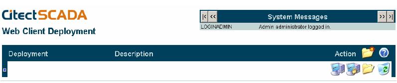
This communication is automatically ‘Port Forwarded’ to 192.168.0.2:80, where it will connect to the WebServer, and you will be presented with the screen below:
Creating a Deployment, with ‘Address Forwarding’
In Citect v7.0, the ‘Network Addresses’ of each Server are hard-coded within the project, i.e 192.168.0.3. However, the Web Client will not be able to connect directly to these IP addresses.
Hence, we need a mechanism of telling the Web Client to use a different IP address.
This is where the INI section [AddressForwarding] comes in.
In order to manage this remapping, the easiest way to configure this is on the ‘Edit Deployment’ page of the Web Server interface.
Under ‘Server’, ‘IP Address’, and ‘Port’ we need to fill out an entry for each SCADA server that we want the Web Client to talk to. These should be in the following format:
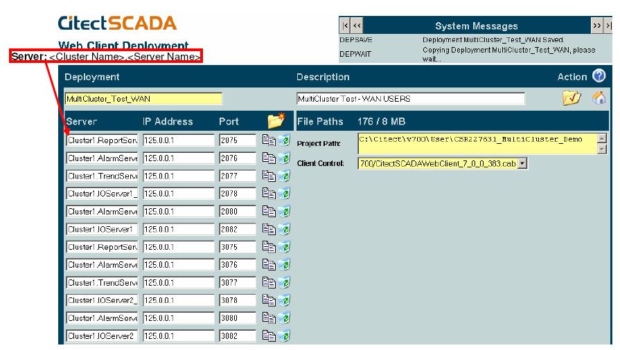
After Applying changes, and expanding the deployment entry:

Note: For more information on the special ports, ‘<I/O Server Name>_PeerPort’ and ‘<Alarm Server Name>_AlarmProps’, please consult the Help file.
[AddressForwarding]
Cluster1.ReportServer1=125.0.0.1:2075
Cluster1.AlarmServer1=125.0.0.1:2076
Cluster1.TrendServer1=125.0.0.1:2077
Cluster1.IOServer1_PeerPort=125.0.0.1:2078
Cluster1.AlarmServer1_AlarmProps=125.0.0.1:2080
Cluster1.IOServer1=125.0.0.1:2082
Cluster1.ReportServer2=125.0.0.1:3075
Cluster1.AlarmServer2=125.0.0.1:3076
Cluster1.TrendServer2=125.0.0.1:3077
Cluster1.IOServer2_PeerPort=125.0.0.1:3078
Cluster1.AlarmServer2_AlarmProps=125.0.0.1:3080
Cluster1.IOServer2=125.0.0.1:3082
The Web method is by far the best and easiest to maintain, however, we could add these to the Web Client’s INI file manually.
Since we only want these settings on the Web Client, and not on the Server’s INI, we would need to make the changes to the INIs at either of the following two stages:
- On the
Server, in the C:\<User>\<Project
Name>\WebDeploy\Citect.ini file, after ‘Preparing
the deployment’ but before Creating / Editing the
deployment.
- This will ensure that the modified file does not get over written during the ‘Preparation’ process, which copies the Server’s INI to the ‘WebDeploy’ folder.
- This will also ensure that once the file has been modified, it is then copied to the Web Server during the ‘Deployment’ stage.
- This will need to be done every time the project is changed, and a new deployment created.
OR:
- After preparing and deploying the project to the Web Server, Edit the Citect.ini file on the Web Server itself, before the Web Clients connect.
Running Both WAN and LAN Web Clients
|
WebServer 192.168.0.2 |
|
|
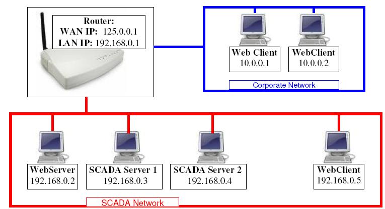
To run both the Wider Area Network (WAN) and LAN clients you need to define two separate web deployments.
This is because the WAN Web Client uses the WAN IP address of the router, which the LAN Web Client cannot access.
However, since the Web Client on the SCADA Network can access the original IP Addresses that have been compiled into the SCADA Projects themselves, no [AddressForwarding] parameters should be required, so simply create a duplicate deployment, but with no additional details about the IP Addresses of the server etc.
You will then end up with two deployments to choose from on your main page. Ensure they are labeled well, so that LAN and WAN users know which deployment to use.
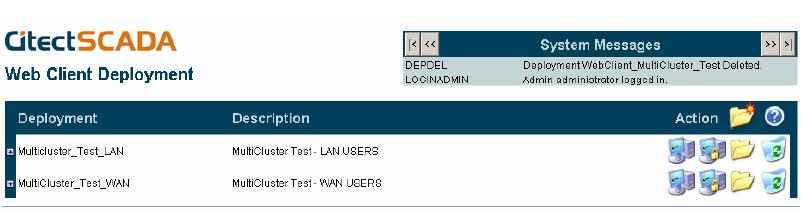
After expanding the options for each, we can see that the WAN USERs version has had these ‘Address Forwarding’ applied, whereas the LAN USERs version is using the default IPs contained within the project.
Web Clients on the WAN will only be able to get Communications using the second deployment, and Web Clients on the LAN will only be able to retrieve Communications using the first deployment.

Troubleshooting -
On the server, in windows firewall, check that port 80 is added
Related Links