
Comport is an abbreviation for "communications port". The Comport is the physical or virtual link from your SCADA node to the automation device. This example is for a Modbus RTU TCP/IP PLC. Many PLCs use the Modbus TCP/IP protocol. This step-by-step example also applied to ADAM 5000 Ethernet driver (ADAM5KE), ADAM 6000 (ADAM6K), Wago 750 (WAGO750) and other drivers.
The Comport for TCP/IP driver is a virtual port. It uses the Network Interface Card (NIC) on the SCADA node. You can create multiple comports on a SCADA Node which all use the same Ethernet card (or multiple NICs). The SCADA node kernel will search all NICs for the IP address specified allowing you to use multiple networks cards on a PC. Alternatively, you may want to create multiple Comports that use the same network interface to create multiple-threads, one for each device or group of devices. WebAccess scans each device in on each comport sequentially. Using multiple comports may be helpful in optimizing communications to multiple PLCs over there same network.
From Project Manager ( See 2.3.2 Connect to Project Node if you need help connecting)
1. Select your SCADA node under the Project/Node list.

2. Select Add Comport
This can take a long time while tables are created in the database on the Project Node / Web Server.
3. The Create New Comport page appears.
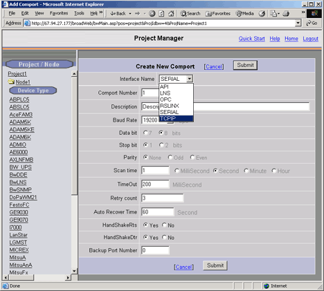
4. Select the TCP/IP as the Interface Name for this Comport. (Also called the Comport Type).
The fields change depending on the Comport Type.
5. The TCP/IP Comport Properties page appears.
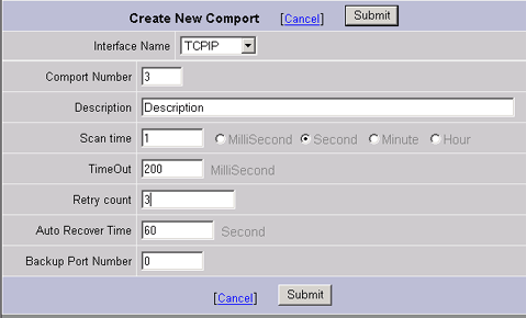
TCPIP - TCP/IP (transmission Control Protocol / Internet Protocol). Specifies a "Virtual Port" that uses the TCP/IP service installed. Does not correspond to specific IO card or comport number. Will access any IO card that uses the TCP/IP service installed on your PC. For a description of the data entry fields for a TCP/IP Network Interface see, section 3.3.4 TCP/IP Com Port Properties.
6. Enter a Comport Number. It is recommended to use a number above 2 so you don't interfere with adding a serial comport. Most PCs have 2 serial comports, if you configured a TCP/IP comport as 1 or 2, you would not be able to use that serial comport in the future. It is not easy to change comport numbers.
7. Optionally, enter a Description. This is just for your own reference.
8. Enter a Scan Time and select the radio button for the units (Millisecond, Second, Minute or Hour).
All devices are scanned at the same frequency on a given comport. All Constant Scan type Tags are scanned at the same frequency on a comport. Display Scan Tags are scanned at this same frequency, but only when they appears on a Display.
9. Accept the default values for the other fields, or modify them. For a description of the data entry fields for a TCP/IP Network Interface see, section 3.3.4 TCP/IP Com Port Properties.
10. Click Submit.
11. The SCADA Node page appears. The Port should appear as a folder under the SCADA node. (In this example Port 3 under Node 1) in the menu tree at left.
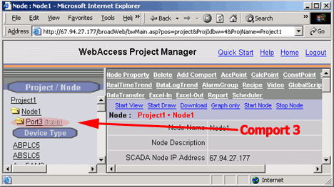
12. Click on the Port hyperlink (Port3 in this example). The Com Port Properties page opens.
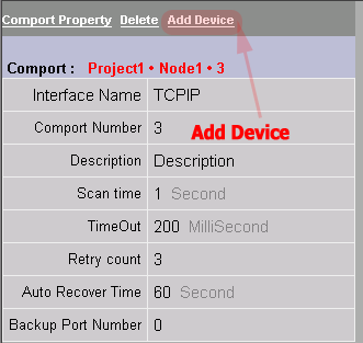
13. Select Add Device.
14. The Create Device Page opens. This also can take some time while datatables are created in the database on the Project Node.

15. Select Modicon form the Device Type pull down list.
(Alternatively, you can select one of the other Modbus TCP/IP devices: ADAM 5000 Ethernet driver (ADAM5KE), ADAM 6000 (ADAM6K), Wago 750 (WAGO750))
16. Enter a Device Name. This will appear as a folder under the comport in the Project Manager. It will also appear in VIEW during runtime in the Point Detail Display for any tags created.
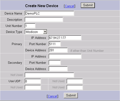
17. Optionally enter a description.
18. Enter the Unit Number. This number will appear in VIEW during runtime on the Station Status display and will be the reference to Enable and Disable communications to the Device. It also will be the reference for communication alarms. (1 to 254)
Logically, this usually matched the actual device number, but it is possible to assign a unit number for VIEW users which does not match the actual Modbus Protocol Device Address. For example, each Modbus PLC has a unique IP Address and all PLCs have Modbus Device address of 1 at these unique IP Addresses.
19. Enter an IP Address for the Device.
20. Enter the TCP or UDP Port Number for the Device.
21. Enter a Device Address if different from the Unit Number.
22. Optionally add Address and Port information for a redundant communication path to the Device. For example, if the PLC has two Network Interface Cards (NICs).
23. If using TCP (the official Modbus Ethernet protocol) leave 0 for Use UDP.
24. Press Submit. This can be a wait while datatables are created on the Project Node.
25. The Update Device Page Appears.
26. Select Add Tag.
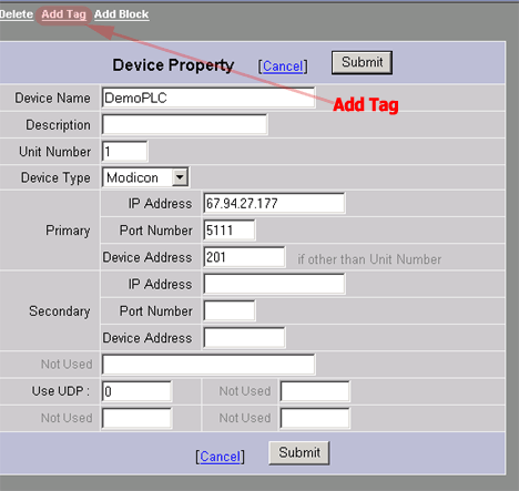
27. The Create New Tag page appears.
28. Select the AO Parameter from the Parameter Pull Down List.
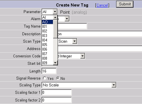
30. The AO Parameter Page opens.
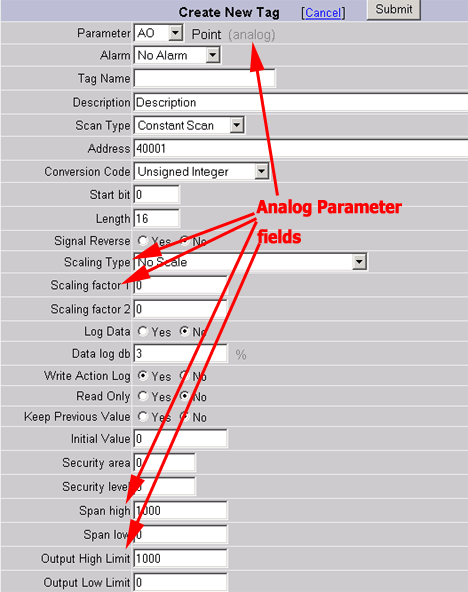
Notice that the Address field changes from 3001 (for AI) to 4001 (for the AO Parameter).
29. Select DO from the Parameter Pull Down List (you have to scroll down to the bottom of the list.
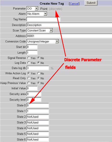
Notice that the Address field Changes to data type changes from analog to discrete. Also, the Data Fields change: State Descriptors appear. There is no Scaling, Span or Output Limits for a Discrete.
Also notice how any data entered is lost if you change the Parameter before pressing submit! It is best to select Parameter before entering tag name. You cannot change the parameter type of a tag once it is created.
30. Select DO if you have not done so already.
31. Select Alarm from the Pulldown list.
Similar to changing the Parameter, selecting alarm changes the page and you will loose any data entered before pressing submit. You can add or remove alarming for a tag after you create.
The page refreshes and alarm fields appear at the top and bottom of the page.

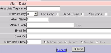
32. Enter a Tag Name. This will be how the information is referenced on Displays in VIEW. Typical Tag names are YS1001, SS4516, Pump_Start, B31_R11_STATUS. The end user usually has a Tag naming convention used at his facility. Tag name is 21 characters Maximum. For legal tag name characters, see 4.11.1 Legal_characters in a Tag Name.
33. Enter a Description. This will appear in VIEW and helps operators identify the information. It will also appear in the Alarm Summary and will be read by the Text-to-Speech Alarm Annunciator. The Description can be changed during runtime by modifying the DESCRP field associated with the tag.
34. Enter the actual Address for the Tag. The parameter provides an example of a typical address for the Data type (00001 for Discrete Outputs, 10001 for Discrete Inputs, 30001 for Discrete Outputs and 40001 for Analog Outputs).
35. For this example,
leave the default settings for
Scan Type = Constant Scan
Conversion Code = Unsigned Integer
Start Bit = 0
Length = 1
Signal Reverse = No.
For more
information on these fields see 4.3 Discrete Tag
Properties
36. Enable Data Logging for the Tag by selecting the radio button next to Log Data.
37. Modify the State0 and State1 descriptors to read ON and OFF.
![]()
38. Modify the Alarm Priority to 1 or higher. An alarm priority of 0 = no alarms.
39. Optionally enable Play Voice to here a Text-to-Speech Alarm annunciation on the SCADA Node.
40. Optionally enable Send Email and enter your email address in the Email To fields to receive an Alarm Email.
41. In this example, leave the other fields at their default values. For more information on these fields see 4.3 Discrete Tag Properties.
42. Press Submit.
43. The Tag Name appears under the Device Name in the Project Manager (Node1, Port3, Demo PLC in this example.)
44. Next Steps are to:
44.1 Download the database to the SCADA Node
44.2 Start the Node (if it was not already running)
44.3 Start View
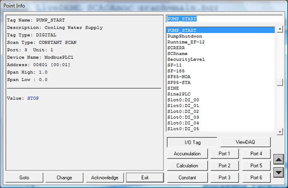
44.4 Open the Point Info dialog Box
44.4.1 Scroll down (if necessary) to see the Tag.
44.4.2 Click on the Tag Name
44.4.3 You should see a ON or OFF as the value. It maybe be flashing Red if in Alarm.
45. If you see an asterisks (*) with a number (typically 8000), communications has failed. You have either the IP Address wrong, the port wrong, the address wrong or some other communication problem.
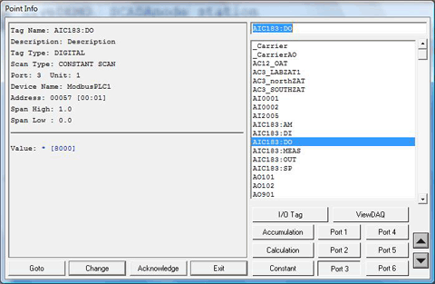
Figure - BAD communications
46. Go to the Station Status Display.
47. If the Device is Blue, this implies you have the Tags Address wrong (e.g. the Modbus Address, 00001, 00002, 00003, etc.)
48. If communication to the Device failed, it will be flashing RED. This implies you have the IP Address, TCP Port or Device Address wrong.
48.1 Try to ping the PLC Address from the Windows Command prompt. See 22.2.11 PING to test TCP/IP communications.
48.1 Confirm the TCP Port and Modbus Device Address from the PLC Configurator or Jumper settings on its Network Card (NIC).