A Serial Port is an RS232, RS422, RS485 or other port on your SCADA node PC identified as COM1, COM2, COM3, COM4, etc. Serial type Devices usually have a "native" driver written by WebAccess. It is possible to have a Serial connection to the device, but use the API or OPC Port Types in WebAccess.
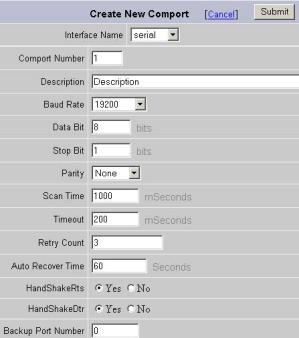
Figure 3-5Comport Properties - Serial
The following Parameters appear for a Serial Type Port.
Serial - Standard Serial Communications Port using the IBM standard for Personal Computers (RS232-C, RS-422 or RS4-85). For more information, see 3.3.2.1 Interface Name
The physical Communications Port on the SCADA Node PC. 1 is COM1, 2 is COM2, 3 is COM3, etc. Selecting Serial means to access the serial Comport with this same number.
User defined field for reference. This appears only in Project Manager.
Describes the speed of communication. Usually, the Field Device determines this. The Baud Rate of the SCADA node must be the same as the baud rate of ALL the field automation devices attached communicating on this communication port. Baud roughly translates into bits per second. A slower baud rate allows noisier connection or longer cable lengths. Refer to your device interface manual to determine the value for this field or the Ladder Logic or other program installed in your field automation device. Sometimes dip switches or jumpers on the field device set this.
Describes the size of the DATA in each message. It must match that specified in each automation field device. Usually determined by the protocol data bits. Refer to your device interface manual to determine the value for this field. Sometimes the Ladder Logic or other program installed in your field automation device sets this. Sometimes dip switches or jumpers on the field device set this.
Usually, there may be 5, 6, 7, or 8 data bits, depending on the device. Almost all devices transmit data using either 7 or 8 data bits
Specifies the number of stop bit period to determine end of data. Refer to your device interface manual, the Ladder Logic, or other program installed in your field automation device to determine the value for this field. Sometimes dip switches or jumpers on the field device set this.
After the data has been transmitted, a stop bit is sent. A stop bit has a value of 1 as a mark state. It can be detected correctly even if the previous data bit also had a value of 1. This is accomplished by the stop bit's duration. Stop bits can be 1, 1.5, or 2 bit periods in length.
Parity is usually either Even, Odd or None.
Parity affords a small amount of error checking, to help detect data corruption that might occur during transmission an additional bit called a parity bit may optionally be transmitted along with the data.
Both the comport and the field devices must use the same parity setting: even parity, odd parity, or none at all.
When even or odd parity is being used, the number of marks (logical 1 bits) in each data byte are counted, and a single bit is transmitted following the data bits to indicate whether the number of 1 bits just sent is even or odd.
For example, when even parity is chosen, the parity bit is transmitted with a value of 0 if the number of preceding marks is an even number. Odd parity is just the opposite, and the parity bit is 0 when the number of mark bits in the preceding word is an odd number.
Parity error checking is very rudimentary. While it will tell you if there is a single bit error in the character, it doesn't show which bit was received in error. In addition, if an even number of bits were in error then the parity bit would not reflect any error at all.
This is the frequency of polling request for new data specified in Milliseconds. The speed is largely determined by the PLC or field device and the nature of the network (how many other devices there are, how much data, the protocol, and baud rate). Slower the baud rates and the larger the amounts of information, require slower scan times. Refer to the Device Manufacturer's Manual for information on minimum scan times.
1000 Milliseconds means WebAccess will try to update data once a second. 50 Millisecond scan times are not uncommon for fast serial connections to a single PLC. 50 msec means WebAccess will try to update data is 20 times per second. The Live Demo is connected to a Modicon PLC simulator with a 50-millisecond scan time and a 57600 bps baud rate.
The freshness of the data is largely determined by the protocol, some protocols are report by exception and include Deadbands that must be exceeded before a value is updated.
A zero (0) sets the scan time to scan as often as possible.
Tag Field: SCANTM
Options:
/N - Variable SCAN time for tags on same com port. Variable Scan tag is supported by some device drivers (Modbus and related drivers are examples). The /N option appended to the address of a tag allows user to specify a scan time as a multiple of the scan time specified in Comport Properties. The tag will be scanned at the rate of N * scan time. A modbus example would be 00001/2 meaning it would scan twice the specified SCAN time.
See the device driver guide for specific information.
Time waited before re-sending a communications packet that did not have a reply.
Specifies how long the software waits for a response to a data request, specifically to wait for a reply from one packet. A recommended value is 7 to 10 ticks, longer if the communication device is slow. This is protocol dependent: some protocols do not allow changes in time out.
Combined with Retry count, also determines time to consider a device or port as BAD. Timeout is the time to wait since last communication packet sent without a reply. Time is in milliseconds. The slow or poor quality communications require longer timeout. The faster the communications network or device, the shorter the timeout required. Shorter timeouts notify operators of communications failure more quickly.
Number of times to retry communications if no reply is received from a device. Combined with Timeout, also determines time to consider a device or port as BAD.
In addition, Indicates the number of times after the first attempt has failed that communication should be attempted before indicating a failure. Specifically, how many times to send a single packet after the field device fails to respond to the first packet. After the retry count is exceeded, all the tags in the packet are marked with asterisks and the next packet of requests is sent. A reasonable value is 3 to 5 times. After this number of tries, the tags in this packet are marked as "fail to respond" (i.e. asterisks) and are disabled. In reality, increasing the number of retries hides failures on the part of the field device to respond to a request. Essentially, increasing the retries gives the field device more chances to reply.
Auto Recover Time is the time to wait before attempting to re-establish communications with a BAD device or port.
Is RTS (Request To Send) signal raised and lowered on the Serial Communications Port. RTS is determined by settings in the field device. Refer to your device interface manual to determine the value for this field and the type of cable used. Some WebAccess Drivers ignore this and leave RTS always ready. See the specific WebAccess Driver Manual for your device.
A Personal computer is a DTE device, while most other field devices are usually DCE devices. If you have trouble keeping the two straight then replace the term "DTE device" with "SCADA Node" and the term "DCE device" with "field device" in the following description.
RTS stands for Request To Send. This line and the CTS line are used when "hardware flow control" is enabled in both the DTE and DCE devices. The DTE device puts this line in a mark condition to tell the remote device that it is ready and able to receive data. If the DTE device is not able to receive data (typically because its receive buffer is almost full), it will put this line in the space condition as a signal to the DCE to stop sending data. When the DTE device is ready to receive more data (i.e. after data has been removed from its receive buffer), it will place this line back in the mark condition. The complement of the RTS wire is CTS, which stands for Clear To Send. The DCE device puts this line in a mark condition to tell the DTE device that it is ready to receive the data. Likewise, if the DCE device is unable to receive data, it will place this line in the space condition. Together, these two lines make up what is called RTS/CTS or "hardware" flow control. The Software Wedge supports this type of flow control, as well as Xon / XOff or "software" flow control. Software flow control uses special control characters transmitted from one device to another to tell the other device to stop or start sending data. With software flow control the RTS and CTS lines are not used
Is DTR (Data Terminal Ready) signal raised and lowered on the Serial Communications Port. Determined by settings in the field device and the type of cable used. Most WebAccess Drivers ignore this and leave DTR always ready. See the specific WebAccess Driver Manual for your device.
DTR stands for Data Terminal Ready. Its intended function is very similar to the RTS line. DSR (Data Set Ready) is the companion to DTR in the same way that CTS is to RTS. Some serial devices use DTR and DSR as signals to simply confirm that a device is connected and is turned on. The Software Wedge sets DTR to the mark state when the serial port is opened and leaves it in that state until the port is closed. The DTR and DSR lines were originally designed to provide an alternate method of hardware handshaking. It would be pointless to use both RTS/CTS and DTR/DSR for flow control signals at the same time. Because of this, DTR and DSR are rarely used for flow control.
This enables a redundant communications path to the Device. If communications can not be established through this Comport, WebAccess will try a second Comport, specified as the Backup Port. You must configure the backup Port number in WebAccess, but without any devices on it. Usually the device must have two comports also. Not all Device Types support a backup Port.
The Backup Port is usually configured as the same type. However, some Device Types allow the backup port to be another physical type; for example, Modicon Device can use a TCP/IP (network) port as a backup port to a Serial Port.
See the specific WebAccess Driver Manual for your device.