A limited version of the Proficy Driver Configuration is used to set an address for your point.
![]() Note: In the Proficy Driver Configuration,
points are called aliases.
Note: In the Proficy Driver Configuration,
points are called aliases.
To open the Proficy Driver Configuration:
Select the ellipsis button beside the Address field in the Device Point Properties tab.
Select the Device Name you want to configure an address for.
Select IO Alias or System Alias.
Click .
Result: The Proficy Driver Configuration appears.
Point Configuration – Point Polling Address (I/O Alias)
Point Addresses using the Proficy Driver Server use the format of [Device Name];[Point Address]. The device name corresponds to devices configured in the Proficy Driver Configuration and the Point Address is specific to the type of protocol the device is associated with. The following figure illustrates the configuration of a point with the Proficy Driver Configuration.
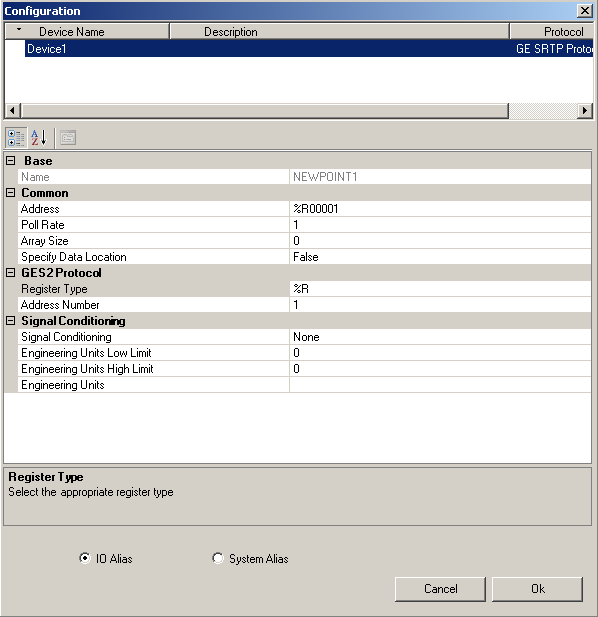
To configure an I/O Alias, enter information in the Configuration dialog box as follows:
|
Name |
A unique name for your point (alias). |
|
Poll Rate |
The rate at which polling occurs using the time format: days:hours:minutes:seconds.tenths of a second. The maximum rate is 6:23:59:59.9. The default is 01. Zero is disabled. |
|
Data Type |
The requested data type to convert the alias into. The valid data types are: DEFAULT, SINT, INT, DINT, USINT, UINT, UDINT, REAL, LREAL, STRING, and BOOL. More data types may be available depending on the protocol. |
|
Array Size |
The number of elements in an array. Zero indicates this alias is not an array. The valid range of entries is 0 through 10,000. Not all protocols support arrays. |
|
String Length |
The number of characters of a string type alias value to read. The valid range of entries is 1 through 999. The default value is 32. |
|
Specify Data Location |
If you set this property to True, the Data Location property is made visible. The property is hidden by default. The valid options are True or False (default). |
|
Data Location |
The data location for reads and writes to sub-register data. By default, sub-register reads and writes communicate with the data location of 0. The valid options are 0 or 1 for bytes and 0 through 15 for bits. The default is 0. For integer (INT) or larger data type settings, this property is not applicable. |
|
Signal Conditioning |
You can use this property to select a signal conditioning option for data manipulation. Signal conditioning scales the raw values received into a different range of values depending on the parameters supplied. This scaling can make raw data meaningful to you. The valid signal conditioning options include None, 8BN, 8AL, 12BN, 12AL, 13BN, 13AL, 15BN, 15AL, LIN, 3BCD, and 4BCD. More signal conditioning options may be available depending upon the protocol. |
|
Engineering Units Low Limit |
Minimum value The smallest value, in engineering units, that is displayed as a value. The default is 0. The minimum valid low limit is -1.79E+308. |
|
Engineering Units High Limit |
Maximum value The largest value, in engineering units, that is displayed as a value. The default is 100. The maximum valid high limit is 1.79E+308. |
|
Engineering Units |
The range for the engineering units. Engineering units are used to linearly scale variable values from external sources, such as devices on your device network using I/O. |
|
Deadband |
An integer value that represents a percentage of deviation that needs to be exceeded before an item's value changes. It works in cooperation with engineering units high and low limits. Enter this value as a number between 1 and 100, representing a percentage of the full engineering units (EGU) range of the item. |
When you have finished configuring the properties of your point, click OK and you will return to the Device Point Properties tab.
The configured address displays in the Address field of the Device Point properties tab.
An example of a configured address is:
Device1;%R00001
![]()
Point Configuration – Diagnostic Point (System Alias)
The following figure illustrates the configuration of a diagnostic point with the Proficy Driver Configuration.
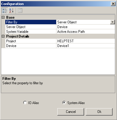
To configure a System Alias, enter information in the Configuration dialog box as follows:
|
Name |
Create a unique name for your point (alias). |
|
Filter By |
The property you select to filter by. If the properties are categorized, the selected property option takes the second row of listed properties and the other property takes the third row. The valid options are System Variable and Server Object. |
|
Server Object |
The available Server Object options vary according to the System Variable selected. For a complete list of all server objects, refer to the System Alias Properties section in the Proficy Driver Server Help. |
|
System Variable |
System variables are special variables that provide information about the computer or system that your application runs on. The available System Variables are modified according to the Project Details Properties selected. For a complete list of all system variables, refer to the Statistics section in the Proficy Driver Server Help. |
The Project Detail properties displayed are made available according to the System Variable selected.
When you finish configuring the properties of your point, select OK and you will return to the Device Point Properties tab.
The configured address displays in the Address field of the Device Point properties tab.
Example
An example of a complete address is
"<SystemItem Project="HELPTEST" Device="Device1" id="ActiveAccessPath" />".
![]()
|
|
Configure Proficy Driver Server points. |
|
|
Set Device Point properties. |