When implementing CitectSCADA for a large application, you can visualize the plant as a series of discrete sections or areas. You can define areas geographically (especially where parts of the plant are separated by vast distances or physical barriers) or logically (as discrete processes or individual tasks).
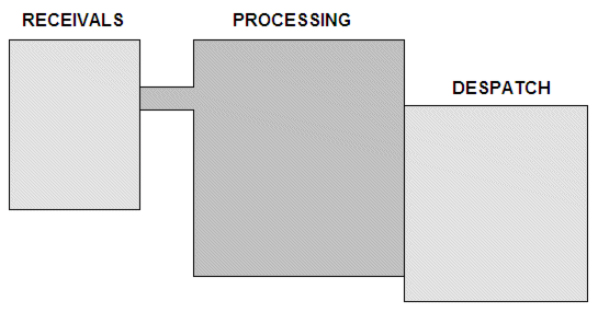
Small plants, for example a simple manufacturing plant can be divided into just three areas - raw product arrives in the receivables area, is transported to an area for processing, and is then transported to a packaging or despatch area.

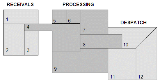
However, with larger or more complex plants you might need to define several areas, like this:

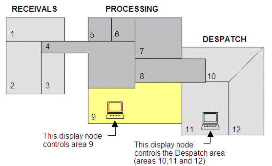
When defining an area, you would usually encompass
a section of the plant that is controlled by one operator (or
controlled from one CitectSCADAControl
Client ).
).
You can also define smaller areas that are collectively controlled by an operator or Control Client. This method can increase flexibility, but can introduce a higher level of complexity to your system.

You can define up to 255 separate areas. You can then refer to these areas by number (1 to 255) or use a label to assign a meaningful name to the area (for example receivables, pre-process, conveying, etc).
After you have defined your areas, you then configure the system elements (commands, objects, alarms, reports, etc). your operators will use in those areas. For example:
For example:
|
Command |
CONVEYOR = 1; |
|
Area |
8 |
|
Comment |
This command belongs to Area 8 |
In this example, an operator without access to Area 8 will not be able to send the command. Refer to Roles for more information on how areas and roles work together.
Note: Any system element that is not assigned to an area between 1 and 255 is automatically placed in a default area known as Area 0. Every user can view the system elements in Area 0, but without the matching privilege will be unable to control them.
See Also