Driver-specific functions |
This driver supports the following functions:
|
Driver supports: |
True/False |
|---|---|
|
RDA |
False |
|
Blockwrite |
False |
|
Real-time capable |
False |
|
Serial logging |
False |
|
Modem capable: |
True |
|
Protocols |
|
|
Spontaneous communication |
False |
|
Polling communication |
|
|
Online browsing |
|
|
Offline browsing |
|
Logging mechanisms
|
|
|
This function is only available in the SYS2000LOG driver |
In the Brodersen System 2000 modules data can
be stored and read offline. For this mechanism we implemented 2
data types "RDA-DATA" and "Trigger".
Generally, the logging mechanism of Brodersen System 2000 is used
in connection with the zenon RDA (RealtimeDataAcquisition) of the
archiving module.
You can use different LogIDs in the System 2000 in order to store
different time grids, for example.
A line from the logging buffer, for example, looks like this:
06.01.2001 18:13:30.00;1;2249;0;1;1
The first entries are date and time. The following ones, separated
by semicolons, are:
LogID, here 1
and then the values of this record.
You can access the single values within this record via the word
offset in the variable definition.
The definition of the data points for this LogID 1 looks as
follows:
Logging of the LogID:
Net No = 1
Node No = 1
LogID = 0 ( don´t care)
Wort No = 0 - Index 0 always LogID
First reference data word :
Net No = 1
Node No = 1
LogID = 1
Wort No = 1 – Index 1 : First reference data word
Second reference data word :
Net No = 1
Node No = 1
LogID = 1
Wort No = 2 – Index 2 : Second reference data word
.......
in the LogID 1, there is a total of 4 reference
data words.
A LogID can also indicate an error or status. LogIDs above 130
indicate an error. You can evaluate them quite simply by using the
zenon reaction matrices.
06.01.2001 19:58:40,00;1;4095;0;0;0
06.01.2001 19:58:40,00;2;4095
06.01.2001 19:58:40,00;3;0
06.01.2001 19:58:40,00;4;0
06.01.2001 19:58:40,00;5;0
In the records above we see only one reference
data record for each of the LogIDs 2 to 5 This means: word number 1
for the data point definition.
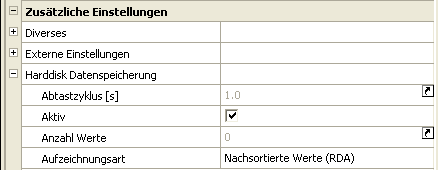
If these values are supposed to be considered in archiving, you
have to specify the following during definition:

This means the option "to harddisk" must be
active and "postsorted values (RDA)" must be specified.
After that you have to create an archive with the defined
variables.
Activating the trigger
There are several options for reading out
data:
Manual trigger:
Define a variable of type Trigger. If a set value is sent to the
variables, the values are read from the hardware and sorted into
the archives. You can limit the number of values that are read by
using a certain value in the set value action. If you write the
value 100 to the trigger variable, 100 records will be read from
the hardware.
I you send the value 0 to the hardware, all available values on the
hardware are read out.
Trigger status
You can monitor the status of the upload of the stored data with the trigger variable. For example, you can define a reaction matrix (REMA) that delivers texts that can look as follows:
|
Value of the trigger variable |
Text to be put out |
|---|---|
|
0 |
Reading data... |
|
65535 |
Data read successfully |
Archiving hints
There are some things regarding the RDA
archives that need to be considered.
First you should ask yourself whether you want to use cyclical or
non-cyclical data (batches). If you have non-cyclical data, create
RDA archives in the zenon archiving module and use batch archiving
for filtering. A new archive file will be created for every read
transaction. The data from the last read transaction can be
displayed and evaluated with the filter option "Last closed
cycle".
If you have cyclical processes, create a normal cyclical archive in
zenon and use the comprehensive time filters of zenon. The archive
files are created in the configured grid and values are sorted in
accordingly.
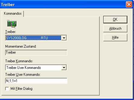
Driver user commands
During Runtime, you can pass on special commands to the driver with the function (variable function) 'driver command'. With N;NetNumber;NodeNumber=0/1 (e.g. N;1;1=1) you can switch the node online / offline. Please consider the separation with semicolons.
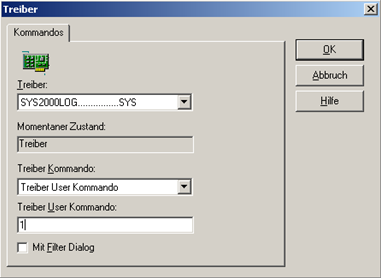
With T;NetNumber;NodeNumber (e.g. T;1;1) you can transfer the local time of the computer to the PLC. With P=0/1 you can activate/deactivate polling. Automatic recognition of a calling station: By default, there is a cyclical check, whether there has been a call to the PC via modem by a station, for which RDA data was defined. If this is the case, all values are read out automatically and sorted into the archives. This automatic check can be disabled with a driver user command.
e.g.:
With this command "1", you switch of the automatic check.