A communication driver is a DLL containing specific information about the remote equipment and implements the communication protocol. Drivers for dozens of common and not-so-common devices are installed with InduSoft Web Studio.
( InduSoft also provides a toolkit to develop new communication drivers. For more information, please contact Customer Support.)
The Drivers task/worksheet allows you to define the communication interface (or interfaces) between the project and remote equipment; such as a PLC, a single-loop, and transmitters.
To configure a communication driver, you must specify the interface parameters (for example, the station address and the baud rate), specify the equipment addresses, and then link them to project tags.
- On the Insert tab of the ribbon, in the Communication group, click Add/Remove Driver; or
- Right-click the Drivers folder in the Project Explorer, and then click Add/Remove drivers on the shortcut menu.
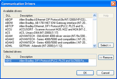
- Available Drivers field: Lists all available drivers and a brief description of each.
- Help button: Click to open the Help menu, which contains detailed configuration instructions for the driver currently highlighted in the Available Drivers field.
- Select button: Click to select the driver currently highlighted in the Available Drivers field.
- Selected Drivers field: Lists all selected drivers and their descriptions (if available).
- Remove button: Click to remove a driver currently highlighted in the Selected Drivers field.
When you click OK in the Communications Driver dialog, you create a subfolder for the selected driver(s) in the Drivers folder located on the Comm tab.
- Serial
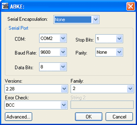
Encapsulation field: Enables serial drivers to communicate
with modem, TCP/IP or UDP connections. This setting is supported
only for serial drivers developed with the UNICOMM library, which
includes most of the serial drivers available in the product.
CAUTION:The Modem option is not supported for Pocket PC v3.00 or older.Note: This section covers only the None option, which enables the driver to connect using a normal serial channel. Please refer to "Using TCP/IP and UDP Encapsulation" and "Using Modem Connections" below for more information about other encapsulation modes. "Serial Encapsulation Tests" below lists the drivers that have been tested with modem, TCP/IP and UDP modes.
- COM field: Click to select a serial communication port.
- Baud Rate, Data Bits, Stop Bits, and Parity fields: Click to select parameters for a serial port configuration.
- Long1, Long2, String1, and String2 fields: These fields are driver custom settings. In the example above, the driver uses Long1 to set up the error detection method and String1 to define the PLC family type.
- Advanced button: Click to open the Advanced settings dialog. Use this dialog to change the default driver parameters.
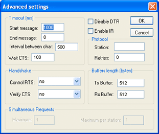
- Timeout (ms)
area:
- Start message field: Specify the timeout for the message start.
- End message field: Specify the timeout for the message end.
- Interval between char field: Specify the timeout between each character.
- Wait CTS field: Specify the timeout for the Clear to Send wait.
- Handshake
area:
- Control RTS drop-down list: Specify whether to use the "Request to Send" control.
- Verify CTS drop-down list: Specify whether to use the "Clear to Send" type of verification.
- Disable DTR checkbox: Click (enable) this box to disable the DTR function (the driver will not set the DTR signal before starting the communication).
- Enable IR checkbox (only available on Windows Embedded target systems): Click (enable) this box to enable the serial driver to use an Infrared interface (COM2 port) instead of a standard serial port to communicate with the device (such as the PLC, I/O, hand-held computers, and so forth).
- Protocol area:
- Station field: Some slave drivers such as the Modbus Slave (MODSL) require a slave network address. Use this field to specify the slave address.
- Retries field: Type a numeric value to specify how many times the driver will attempt to execute the same communication command before considering a communication error for this command.
- Buffers length
(bytes) area:
- Tx Buffer field: Specify the transmission buffer length (in bytes).
- Rx Buffer field: Specify the reception buffer length (in bytes).
- Simultaneous
Requests area (available only on selected drivers):
- Maximum field: Specify the maximum number of requests that may be sent simultaneously to all connected devices.
- Maximum per station field: Specify the maximum number of requests that may be sent simultaneously to a single device.
Note: The maximum number of simultaneous requests depends on the device and protocol specifications. Please consult the device manufacturer's documentation.
- MAIN DRIVER SHEET: Provides the easiest method for configuring communication between project tags and device addresses. This interface allows you to automatically group tags to provide the best performance during runtime. You cannot use this interface to control the time needed to scan a group of tags individually.
- STANDARD DRIVER SHEETS: Allows you to control the time needed to scan a group of tags individually.
You can use both sheets at the same time.
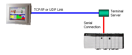
Using TCP/IP and UDP Encapsulation
- Right-click on the driver's folder, and then choose
Settings from the shortcut menu.
This will give you access to the communication parameters.
- In the Serial
Encapsulation field, select TCP/IP or UDP/IP:
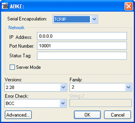
- IP Address field: Specify the IP Address for the Terminal Server. This field accepts tags in curly brackets.
- Port Number field: Enter the TCP/IP or UDP/IP port number.
- Status Tag field: This field is available only when using TCP/IP. The tag on this field receives the value 1 when the TCP/IP connection is established; otherwise, it receives 0.
- Server Mode field: The TCP/IP encapsulation allows the Server Mode, making the remote client responsible for establishing the connection to enable the communication.
Using Modem Connections
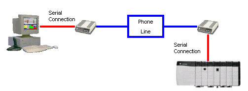
- Right-click on the driver's folder, and then choose
Settings from the shortcut menu.
This will give you access to the communication parameters.
- In the Serial
Encapsulation menu, select Modem:
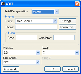
- Name drop-down list: Select the modem that the driver will use to establish the connection. If you do not know the modem name, use the Auto Detect option. The Auto Detect 1 will use the first modem available, Auto Detect 2 will use the second, Auto Detect 3 will use the third, and Auto Detect 4 will use the fourth.
- Phone field: Enter a phone number that the driver will use to connect to the remote device. This field accepts tags between curly brackets.
- Settings button:
Click on this button to configure the modem settings. The window
that displays when you click on this button depends on the
operating system that you are using and on the modem type.
CAUTION:The settings configured by clicking on this button are not saved with your project. The information is saved on the operating system registry, and they are valid only in the computer that you are interacting with. If you install your project on another computer, you will have to reconfigure these settings.
- Connection button:
Click to open the Connection
Control window. The default connection settings should
suffice for most of the projects. However, you can take full
control over the connection, and also enable incoming calls, by
clicking on this button.
Figure 6. Connection Control dialog
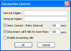
- Dial out trigger field: When the value of the tag configured in this field changes, the driver will try to connect to the remote device. If the connection has already been established, the command is ignored. You do not have to use this field if you are using Auto Connect.
- Hang up trigger field: When the value of the tag configured in this field changes, the driver will disconnect from the remote device. If the device is disconnected the command is ignored. You do not have to use this field if you are using Disconnect call if idle for more than.
- Auto Connect field: When this option is enabled, the driver will try to connect to the remote device before sending any information. If the connection fails, the next attempt will be made after the Retry Interval has expired.
- Disconnect call if idle for more than field: When this option is checked, the driver will automatically disconnect from the remote device if no communication is performed after the time you specified.
- Enable incoming calls field: Check this option if you want to enable the driver to receive calls from the remote device. You can use the Hang up trigger to drop the call once it has been established. Notice that one driver can use both incoming calls and outgoing calls.
- Status area
- Code field: Enter
with a tag that will receive one of the following codes when the
driver is running:
- 0 = Disconnected
- 1 = Connected
- 2 = Dialing
- 3 = Dropping
- 4 = Closing Line
- Description field: Enter with a tag that will receive a complete description of the current status. The description is associated with the Code field; however, it brings some additional information about the current status.
- Code field: Enter
with a tag that will receive one of the following codes when the
driver is running:
Serial Encapsulation Tests
Most of the serial drivers should work with every serial encapsulation mode. However, most of the drivers were developed before the encapsulation modes had been created. The following table lists the drivers fully tested with certain encapsulation modes; if the driver that you intend to use is not listed and you are unsure whether it will work, please contact your distributor.
| Driver | Modem | TCP/IP | UDP/IP |
|---|---|---|---|
| MODSL | X | X | X |
| ABKE | X | X | X |
| MODBU | X | X | |
| OMETH | X |
X = Item has been tested