Connection points of procedural elements |
|
Manual -> Automatic Line Coloring (ALC) - Topology -> Engineering in the Editor -> ALC elements -> Procedural elements -> Connection points of procedural elements |
|
|
Connection points of procedural elements |
|
Manual -> Automatic Line Coloring (ALC) - Topology -> Engineering in the Editor -> ALC elements -> Procedural elements -> Connection points of procedural elements |
|
|
The connection of a line to a procedural element (Combined element) is realized with overlapping drawing in the picture an connection points of the combined element. Several lines can be connected to the same connection point at the same time. All lines whose line starts are within the area defined below, are connected (Topology from the graphic).
In the following illustration all possible connection points are shown in detail:
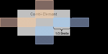
X = 1/3 Width
Y = 1/3 Width (max. 10 pixels)
Z = 1/3 Height
W = 1/3 Height (max. 10 pixels)
|
|
|
If a line is outside the area shown above, there is no connection and thus no coloring. So there will also be no coloring for further lines. |
With sources, sinks and links all described connection points can be generally used.
|
|
|
With sources and sinks only one connection point must be used at the same time. It does not matter which connection point. If different connection points are used at the same time, undefined states can occur. |
Elements of the type link can also use several connection points at the same time. The incoming color information is passed on to all lines.
In switches and transformers the connection 1 (input) is on the left or on the top and connection 2 (outputs) are on the right or on the bottom.
|
|
|
At switches and transformers it has to be cared, that only one input connection and one output connection is used. The simultaneous use of several input or output connection points results in inconsistancies and thus is not reliable. |
|
|
|
For all procedural elements: Only one line can be connected to a connection point. Junctions cannot be realized directly on an element but must be drawn with lines. |