This example uses the Block types provided with the ADAM 5000E device drivers. Specifically to an 5017 IO cards Please refer to Add a Block Type section for information about building new Block Types.
This section also assumes you have configured a Comport and a Device. This example creates a Block for an ADAM 5000E. Refer to 3.1.2.1 Configure a Modbus TCP Port, Device and Tags on for a Step by Step Guide to creating a Comport and Device for an ADAM 5000E.
This section assumes you have started Internet Explorer 6.0 or later Web Browser and connected to your Project Node.
1. Start WebAccess Configuration.
2. Login with User Name and Password.3. Select your Project Name.
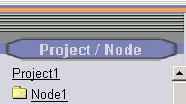
4. The Project Manger opens.
5. You may need to expand the Port List by Clicking on the SCADA Node (Node 1 in the example).
6. You may need to expand the list of Devices under your Comport by clicking on the Comport.
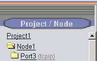
7. Drag the slider bar on the left Frame down to reveal Communication Port (e.g. Port 3 in the example).
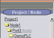
8. Drag the slider bar on the left Frame down to reveal Device (e.g. DemoPLC 3 in the example).
9. Click on the ADAM 5000E Device (in the example, pick DemoPLC).
10. The Device Properties page opens. It can take some time to open all the datatables on the Project Node / Web Server.
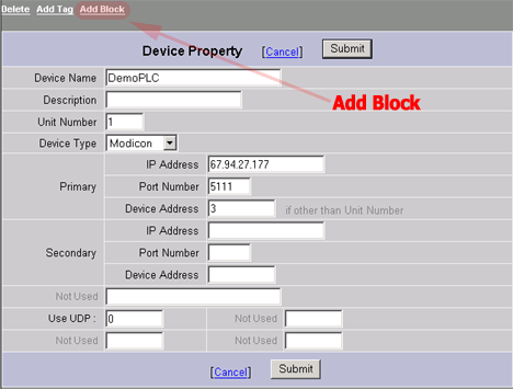
11. Select Add Block.
12. The Create New Block Page appears.
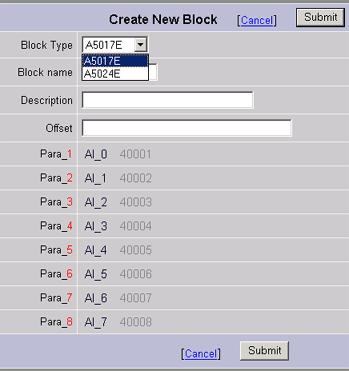
13. Select the A5017E from the pull down list for Block Type.
14. Enter a Block Name. This will become the Tag name for your Block Tag. Block Name is up 12 alphanumeric characters. This is the name that users and operators will use to access the data read by this tag. Typical Block Names are TIC1001, Zone11, and Pump61. See 4.11.1 Legal characters in a Tag Name. For this example, enter SLOT4. This assumes you have an 5024 IO card in the 4th slot of your ADAM 5000e PLC.
15. Enter a Description. This helps operators to identify the tag. It will appear on the Point Info, Block Detail and Point Detail Displays. It will also appear in the Alarm Summary and will be read by the Text-to-Speech Alarm Annunciator.
13. Enter an Offset. If you planned your addresses well, you will be able to use the Block Offset feature to create the proper addresses for all the parameters in the block with a single keystroke. For this example enter 30.
The offset for Modbus protocol devices (and the ADAM5000E) are a simple integer.
Note - for other protocols and device types, it may be a complex series of numbers, commas and letters. Refer to the specific device driver guide for the addresses used by your device.
The Block Offset feature will increment all the addresses of all the parameters in a block by a given amount. If your parameter addresses have a predictable pattern, the Block Offset feature can greatly reduce the time and effort to create blocks and establish communications with the field.
For an ADAM5000, it will add the offset to each Modbus address shown (e.g. 4001, 4002, 4003 and 4004 for a 5024). The offset is zero-based and multiplied by 10. For an ADAM 5000, add the slot number 1 minus 1 multiplied by 10. For example, the offset for Slot 5 is 40. The offset for Slot 4 is 30. The offset for slot 1 is 0. If the offset is 30, the Modbus addresses for a 5024 become 40031, 40032, 40033 and 40034).
For this example enter 30 (this assumes you have a 5024 IO card in the 4th slot of your ADAM 5000E PLC).
14. Select Submit when finished.
15. Next Steps are to:
15.1 Download the database to the SCADA Node
15.2 Start the Node (if it was not already running)
15.3 Start View
15.4 Open the Point Info dialog Box
15.4.1 Scroll down (if necessary) to see the Tag Name for the Block.
15.4.2 Click on the TagName:Parameter for the Block. In this example SLOT4:SLOT4:AO_0.